Cylindrical porous jetting-type miniature liquid combustor and combustion method thereof

A micro-liquid and burner technology, which is applied in the direction of burners, lighting and heating equipment, etc., can solve the problems of sufficient air mixing and difficult rapid evaporation of liquid fuel, etc., and achieve the effects of increasing contact time, convenient ignition process, and accelerating evaporation

Pending Publication Date: 2019-01-18
SOUTH CHINA UNIV OF TECH
View PDF11 Cites 2 Cited by
  • Summary
  • Abstract
  • Description
  • Claims
  • Application Information

AI Technical Summary

Problems solved by technology

[0004] The purpose of the present invention is to overcome the shortcomings of the prior art above, and to provide a cylindrical multi-hole injection micro liquid burner, so as to solve the problem that the liquid fuel that the micro liquid burner has faced for a long time is difficult to quickly evaporate and the air is insufficient. Problems such as mixing, another object of the present invention is to provide a kind of combustion method of the miniature liquid burner of cylinder multi-hole injection type

Method used


Image

  • Cylindrical porous jetting-type miniature liquid combustor and combustion method thereof
  • Cylindrical porous jetting-type miniature liquid combustor and combustion method thereof
  • Cylindrical porous jetting-type miniature liquid combustor and combustion method thereof

Examples


Embodiment 1

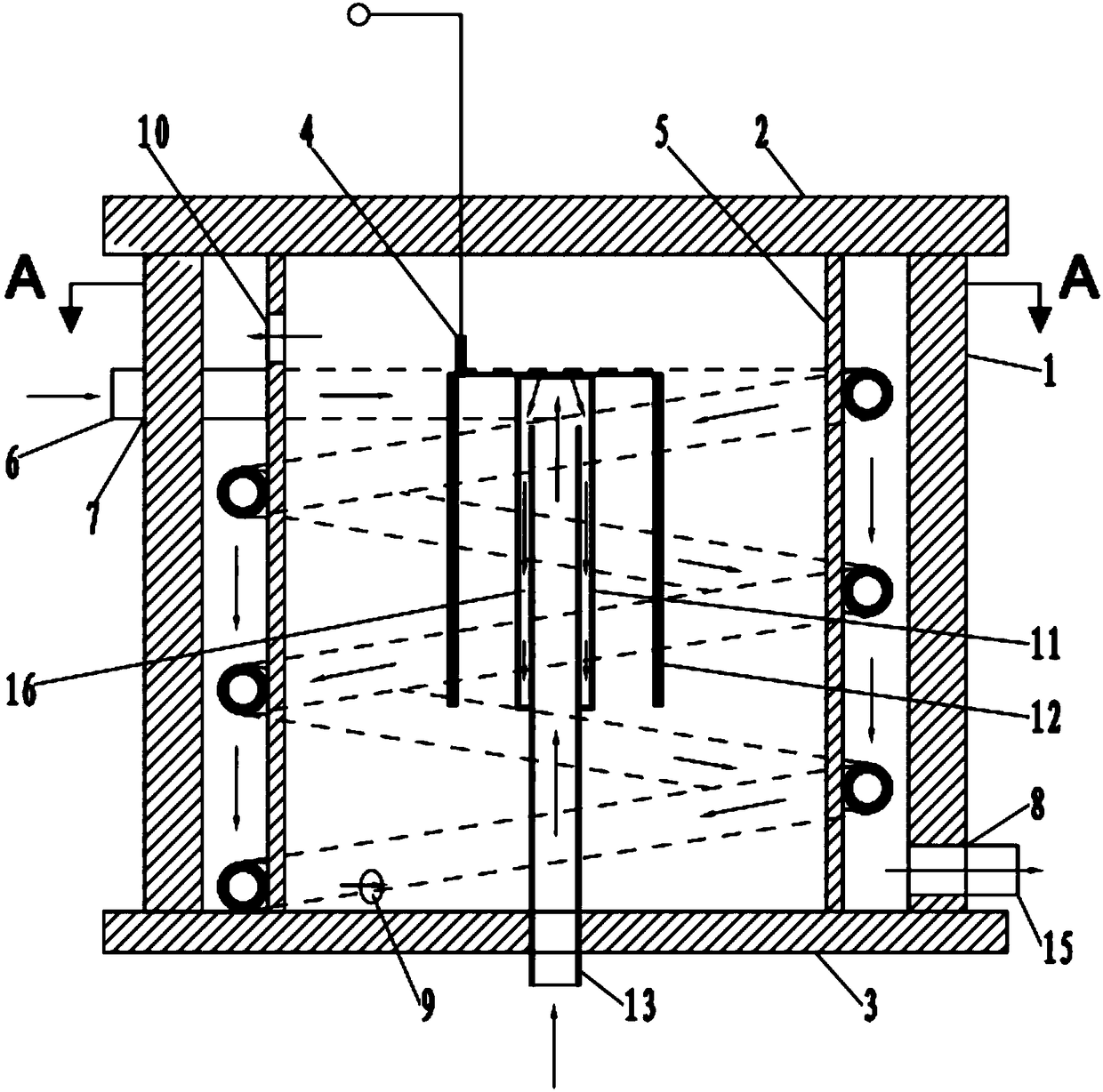
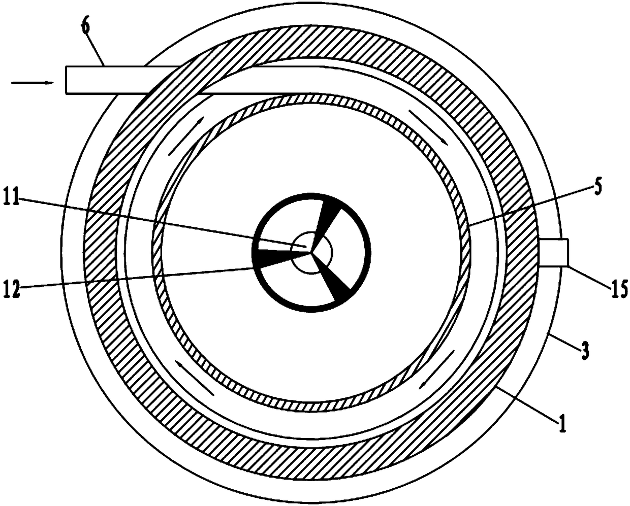
[0032] Such as figure 1 , figure 2 , Figure 5 , Figure 6 A cylindrical multi-hole injection type miniature liquid burner shown includes a combustion chamber 5, an upper sealing plate 2, a lower sealing plate 3, an air intake duct 6 and an igniter 4, and the upper sealing plate 2 is sealed in the combustion chamber 5, the lower sealing plate 3 is sealed to the lower end of the combustion chamber 5, the combustion chamber 5 has a first air inlet 9 and a first exhaust port 10, and one end of the air inlet pipe 6 runs through the first The air inlet 9 is to the inside of the combustion chamber 5, and the inside of the combustion chamber 5 is provided with a feed pipe 13 and a burner, and the burner includes a fuel column 11 and a metal grid sleeve 12, and the metal grid sleeve The bottom end of the cylinder 12 is open, the metal grid sleeve 12 is sleeved on the fuel column 11, the top of the fuel column 11 is sealed, and the side wall of the fuel column 11 has a plurality of...

Embodiment 2

[0043] This embodiment also includes the following technical features on the basis of Embodiment 1:

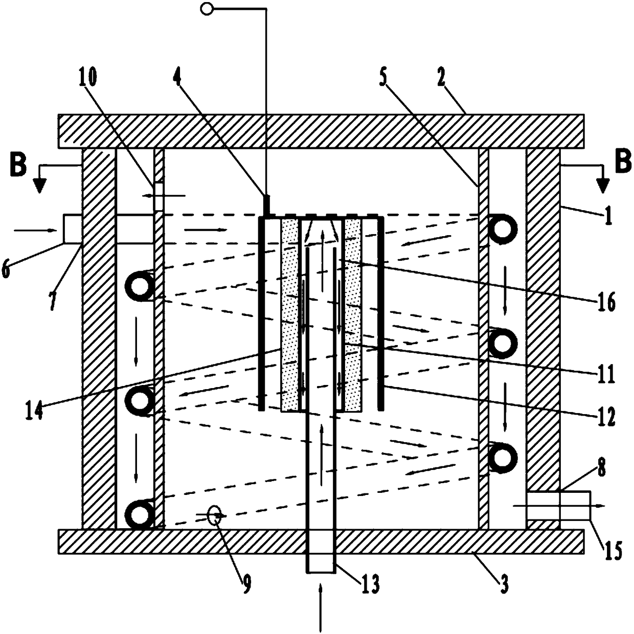
[0044] Such as Figure 3-Figure 6 As shown, the burner also includes a porous medium layer 14 , the porous medium layer 14 is closely attached to the side wall of the fuel column 11 , and there is a gap between the porous medium layer 14 and the metal grid sleeve 12 . The gap between the metal mesh sleeve 12 and the porous medium layer 14 is 2mm, the porous medium layer 14 is attached to the outer sidewall of the fuel column 11, and the porous medium layer 14 is a porous structure, and the discharge of liquid fuel from the fuel column 11 The flow sprayed out from the hole passes through the porous medium layer 14 to disperse and gasify. The porous medium layer 14 increases the evaporation surface area of ​​the liquid fuel, which is beneficial to the dispersion and heat-absorbing evaporation of the liquid fuel. The porous medium layer 14 is made of aluminum foam or ceramic mat...


PUM


Abstract

The invention relates to a miniature liquid fuel combusting device, and discloses a cylindrical porous jetting-type miniature liquid combustor. The cylindrical porous jetting-type miniature liquid combustor comprises a combustion chamber, an upper sealing plate, a lower sealing plate and an air inlet pipeline, the upper sealing plate and the lower sealing plate are used for sealing the combustionchamber, the combustion chamber is provided with a first air inlet and a second air exhaust, and one end of the air inlet pipeline penetrates through the first air inlet and extends into the combustion chamber; the combustion chamber is internally provided with a feeding pipeline and a cumbustor body, one end of the feeding pipeline is located inside the combustor body, the bottom of the combustorbody is connected with the middle of the feeding pipeline, and the other end of the feeding pipeline penetrates through the lower sealing plate. The invention further provides a combustion method ofthe cylindrical porous jetting-type miniature liquid fuel combustor. The miniature liquid fuel combustor and the combustion method thereof have the advantages that the superficial area of liquid fuelis increased, so that the liquid fuel is sufficiently mixed with air, and meanwhile, evaporation of the liquid fuel is accelerated at the same time so that combustion can be stably and efficiently conducted.

Description

technical field [0001] The invention relates to a miniature liquid fuel combustion device, in particular to a cylindrical multi-hole injection type micro liquid burner and a combustion method thereof. Background technique [0002] In recent years, based on the urgent demand for power of emerging micro-aircraft, individual combat systems, micro-robots and various portable electronic devices, most of the devices are driven by traditional chemical batteries and turned to pairs with much higher energy density. Research on micro-combustion power devices based on liquid hydrocarbon fuels based on the energy density of lithium batteries. If they can make them burn stably and efficiently, micro-miniature power devices based on combustion will have great competitiveness. At the same time, liquid hydrocarbon fuels The products of full combustion are water and carbon dioxide, which greatly reduces the pressure on the environment. Therefore, the research and development of micro liquid ...

Claims


Application Information

Patent Timeline
Patent Type & Authority Applications(China)
IPC IPC(8): F23D11/00F23D11/36
CPCF23D11/00F23D11/36
Inventor 甘云华周毅江政纬
Owner SOUTH CHINA UNIV OF TECH
Why Eureka
Try Eureka