Resistance strain-type tubular pressure sensor and pressure site test method
A technology of resistance strain type and pressure sensor, which is applied in the direction of instruments, measuring force, measuring devices, etc., to achieve the effects of fewer sources of measurement errors, low cost, and simple manufacturing and calibration methods
- Summary
- Abstract
- Description
- Claims
- Application Information
AI Technical Summary
Problems solved by technology
Method used
Image
Examples
Embodiment 1
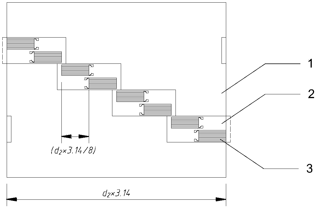
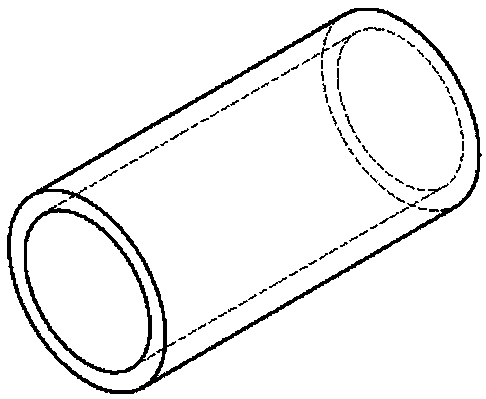
[0042] The resistance strain type circular tubular pressure sensor includes a circular steel pipe section and a foil resistance strain gauge adhered circumferentially along its inner wall. Among them, circular steel pipe sections such as figure 2 As shown, the pasting position of the strain gauge is as follows figure 1 shown. The specific manufacturing process is carried out as follows:
[0043] (1) Manufacturing of circular steel pipe joints for sensor sensitive elements. The 17-4PH martensitic stainless steel rod is subjected to solid solution treatment, and then processed by turning to form a round thin-walled steel pipe section of predetermined size, and then subjected to vacuum aging treatment at 450°C to 480°C. Experimental research shows that aging in this temperature range is 3-4 hours, and the sample structure can obtain tempered martensite, making the hardness reach 39-42HRC, and the yield strength reaches 1180MPa.
[0044] (2) Manufacturing of foil strain gauge...
Embodiment 2
[0047] Combined pressure tube sensor such as Figure 4 , which is composed of pressure sensor tube unit (7) (9), lead pipe (5) (8), and interpolated flexible connector (6) connected in series, and the strain gauge wire (10) is formed by the through internal cavity lead out. According to the number of required measuring points and the spacing of measuring points, the number of sensor tube units of the combined pressure tube and the length of the lead round tube between each tube unit are selected. If it is necessary to connect the wires and the reserved terminals of the strain gauge at the test site, the connection part can be insulated and protected by a thermoplastic tube to avoid short circuits. The external wire and the strain collector form a Wheatstone bridge circuit.
Embodiment 3
[0049] The present invention provides a pressure field test and calculation method corresponding to the sensor, the steps are as follows:
[0050] (1) The measured value ε of all the strain gauges in the pressure sensor pipe joint unit at a certain measuring point is obtained by the strain acquisition instrument i , and then by its mean According to the formula (1), the average value of the confining pressure at the measuring point is obtained
[0051] (2) Use numerical calculation methods such as finite element method to establish the confining pressure load of sensor pipe joints The plane strain model under the action takes the measured values of the strain gauges at each azimuth position as the target result, and takes the average value of the confining pressure load As a known quantity, adjust Until the numerical calculation result of the circumferential strain value of the inner wall of the model agrees with the measured result, at this time That is, the dist...
PUM
| Property | Measurement | Unit |
|---|---|---|
| Yield strength | aaaaa | aaaaa |
| Hardness | aaaaa | aaaaa |
Abstract
Description
Claims
Application Information
 - R&D
- Intellectual Property
- Life Sciences
- Materials
- Tech Scout
- Unparalleled Data Quality
- Higher Quality Content
- 60% Fewer Hallucinations
Browse by: Latest US Patents, China's latest patents, Technical Efficacy Thesaurus, Application Domain, Technology Topic, Popular Technical Reports.
© 2025 PatSnap. All rights reserved.Legal|Privacy policy|Modern Slavery Act Transparency Statement|Sitemap|About US| Contact US: help@patsnap.com


