Connection rod structure-based cascade wind tunnel rotation window support mechanism

A cascade wind tunnel and connecting rod structure technology, which is applied to the testing of machines/structural components, measuring devices, instruments, etc., can solve problems such as increased manufacturing costs, difficulty in rotating windows, and expensive arc guide rails, etc., to achieve manufacturing The effect of simple process, reduced friction and low production cost

Pending Publication Date: 2019-01-18
NORTHWESTERN POLYTECHNICAL UNIV
View PDF0 Cites 3 Cited by
  • Summary
  • Abstract
  • Description
  • Claims
  • Application Information

AI Technical Summary

Problems solved by technology

[0004] But these two kinds of rotating window supporting structures all have obvious deficiencies: in the first kind of structure, turning window can produce bigger pressure to base, thereby produces bigger frictional force, makes the rotation of turning window become very difficult; and in the second structure, although the friction between the guide rail and the turning window can be well controlled, the manufacturing cost will be greatly increased due to the high price of the arc guide rail. unacceptable
In addition, for the horizontal planar cascade wind tunnel experimental equipment, both of these two schemes can only eliminate the downward degree of freedom of the turning window. If the horizontal type is changed to a vertical type, neither structure can play the role of support and fixation

Method used


Image

  • Connection rod structure-based cascade wind tunnel rotation window support mechanism
  • Connection rod structure-based cascade wind tunnel rotation window support mechanism
  • Connection rod structure-based cascade wind tunnel rotation window support mechanism

Examples


Embodiment Construction

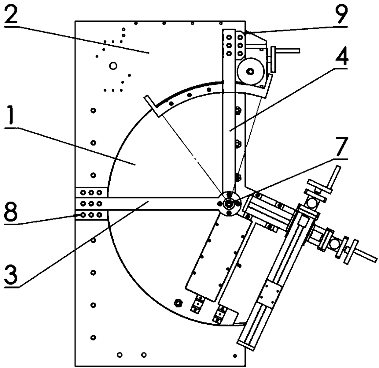
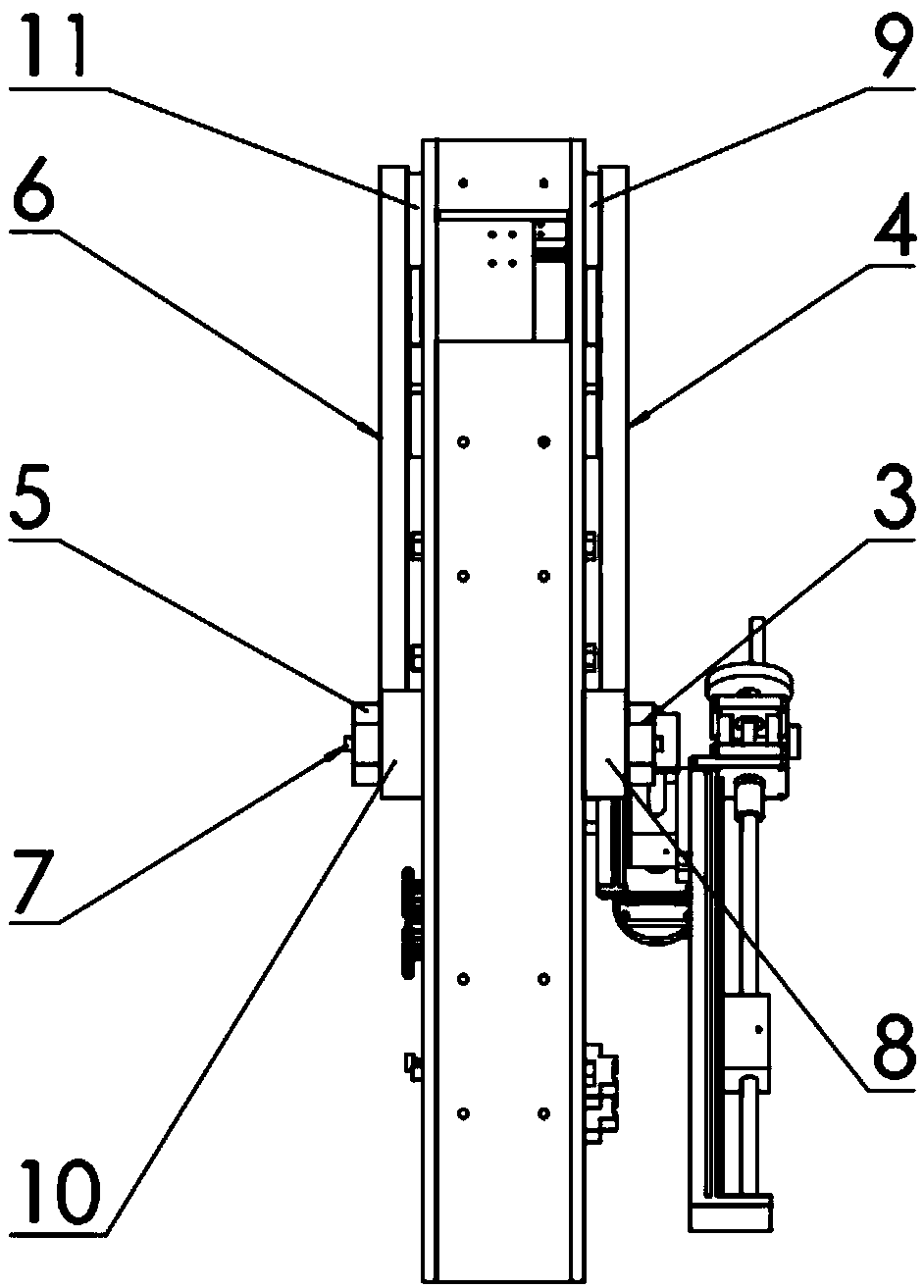
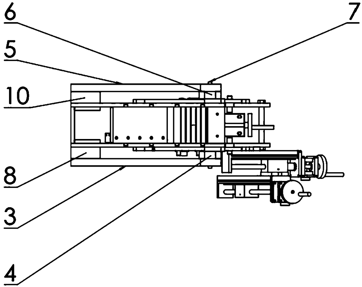
[0022] This implementation example is a support mechanism for a cascade wind tunnel rotating window based on a connecting rod structure.

[0023] refer to Figure 1 ~ Figure 4 , this implementation example is based on the cascade wind tunnel rotating window support mechanism of the connecting rod structure, consisting of the rotating window 1, the base 2, the first support beam 3, the second support beam 4, the third support beam 5, and the fourth support beam 6 , shaft 7, first liner 8, second liner 9, third liner 10, fourth liner 11; wherein, the turning window 1 is a fan-shaped flat plate, and the center of the two turning windows is provided with a center hole and a shaft 7 are connected, and two pairs of support beams are respectively arranged on both sides of the two turning windows, wherein the first support beam 3 and the third support beam 5 are horizontal, and the second support beam 4 and the fourth support beam 6 are vertical Towards. In this implementation examp...


PUM


Abstract

The invention discloses a connection rod structure-based cascade wind tunnel rotation window support mechanism. The connection rod structure-based cascade wind tunnel rotation window support mechanismcomprises rotation windows, a substrate, support beams, a shaft and lining pads, wherein the support beams are in linkage with the rotation windows, the shaft penetrates through a circle center holeof a left rotation window and a right rotation window, two pairs of support beams are arranged at two sides of the rotation windows, one of the two pairs of support beams is in a horizontal direction,the other pair of support beams is in a vertical direction, one end of each support beam is fixedly arranged on the base by a bolt, and a round ring is arranged at the other end of each support beam.Gravity of the rotation windows are borne by the support beams, the strength, the rigidity and the rotation accuracy of the rotation window support mechanism can be improved, and the friction force between the rotation windows and the base is reduced on the premise that the manufacturing cost is not increased; a stable triangular support structure is formed between the support beams at the two sides and the base, all freedom degrees of the rotation windows rotating a part except an axis are eliminated, so that the mechanism is suitable for a horizontal type experiment table and is also suitable for a vertical type experiment table; and the support mechanism is low in production cost and simple in manufacturing cost and is particularly suitable for a planar cascade wind tunnel experiment table for teaching.

Description

technical field [0001] The invention relates to the technical field of gas turbine engine experimental equipment, in particular to a support mechanism for a blade cascade wind tunnel rotating window based on a connecting rod structure. Background technique [0002] A wind tunnel is used to generate and simulate airflow and is used for aerodynamic experimental equipment. Among them, the planar cascade wind tunnel is an important experimental equipment for the design of gas turbine engines, providing an important experimental basis for the design of compressors and turbines. [0003] The rotating window of the cascade wind tunnel is an approximate fan-shaped structure with a circular arc on the edge, which needs to be rotated. The traditional wind tunnel rotating window support mechanism of the cascade is generally divided into two types: one is to set grooves on the contact surface between the base and the rotating window, and the rotating window is matched with the groove o...

Claims


Application Information

Patent Timeline
Patent Type & Authority Applications(China)
IPC IPC(8): G01M9/04G09B23/12
CPCG01M9/04G09B23/12
Inventor 刘汉儒邵琪杰张铮王掩刚
Owner NORTHWESTERN POLYTECHNICAL UNIV
Why Eureka
Try Eureka