Device for perturbation effect and stepwise loading test of rock rheology

A loading test device and test device technology, which is applied in the field of rock rheological disturbance test, can solve the problems of affecting the results, weakening the dependence of the hydraulic system, and large error in force transmission, so as to prevent accidental damage, have good pressure maintaining effect, and convert force Reduced effect

Active Publication Date: 2019-01-18
NORTH CHINA INST OF SCI & TECH
View PDF8 Cites 3 Cited by
  • Summary
  • Abstract
  • Description
  • Claims
  • Application Information

AI Technical Summary

Problems solved by technology

[0002] The existing electro-hydraulic servo principle rock rheometer has the following disadvantages: (1) The stability of the oil pressure system is poor, and there are hydraulic fluctuations, which affect the results of the rock rheological disturbance effect test (the rock rheological disturbance effect test requires a non-fluctuating static load axial pressure); (2) The structure of the system is complex, the precision requirements for parts (such as various hydraulic valves, accumulators, filters, heat sinks, etc.) are high, and the manufacturing cost is high
The existing rrts rock rheological disturbance effect meter is a rheometer combining the principle of electro-hydraulic servo and external gravity loading. This type of rheometer is relatively less dependent on the hydraulic system, but still has the following disadvantages: (1 ) The original axial pressure loading function has a large step-by-step loading level and is instantaneous loading, without low-level continuous slow loading function, and the specimen is prone to accidental damage; (2) The friction force between the wheel disc gears is too large, and the force transmission error is large

Method used


Image

  • Device for perturbation effect and stepwise loading test of rock rheology
  • Device for perturbation effect and stepwise loading test of rock rheology
  • Device for perturbation effect and stepwise loading test of rock rheology

Examples


specific Embodiment approach 1

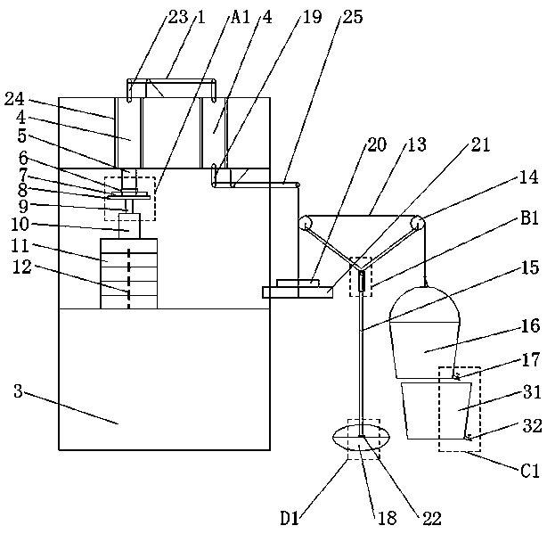
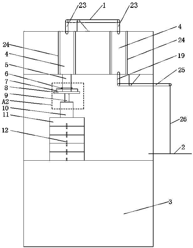
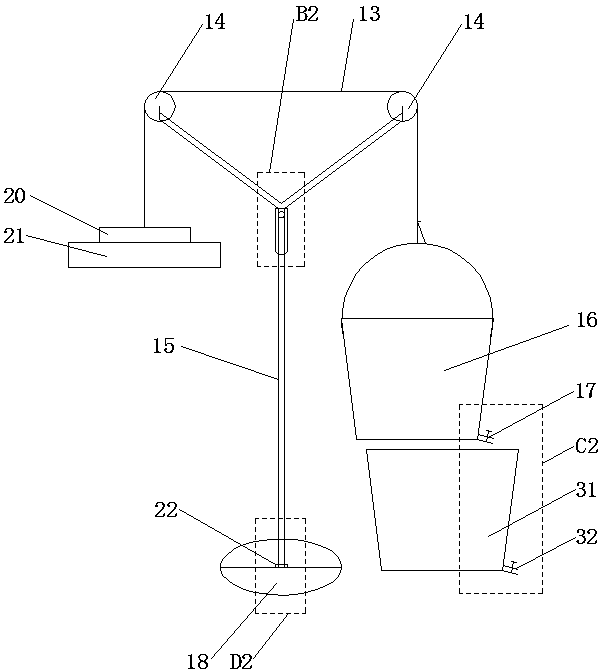
[0023] Specific implementation mode one: as Figure 1-Figure 7 As shown, this embodiment discloses a rock rheological disturbance effect and step-by-step loading test device, which consists of: a rock rheological disturbance effect test device and a step-by-step loading test device; the rock rheological disturbance effect test device includes Loading tray 2, frame body 3, force transmission shaft 5, impact weight 6, disturbance dynamic sensor 7, upper pressure bearing plate 8, pressure sensor 10, connecting rope 26, pad assembly, two sliders 4, two sliders Road 24, two levers and three connecting rods; the two levers are respectively lever one 1 and lever two 25, and the three connecting rods are respectively two connecting rods one 23 and one connecting rod two 19; The step-by-step loading test device includes a force transmission rope 13, a telescopic support 15, a bucket 16, a valve 17, a base 18, a fixed claw 20, a gravity weight 21, a bearing 22 and two fixed pulleys 14; ...

specific Embodiment approach 2

[0042] Specific implementation mode two: as figure 1 , figure 2 As shown, this embodiment is a further description of specific embodiment 1. The backing plate assembly includes a plurality of backing plates 11 and a plurality of fixing nails 12; the plurality of backing plates 11 are stacked in sequence, and each The two backing plates 11 are fixedly connected by fixing nails 12 .

specific Embodiment approach 3

[0043] Specific implementation mode three: as figure 1 , image 3 , Figure 5 , Figure 7 As shown, this embodiment is a further description of specific embodiment 1 or 2. The telescopic bracket 15 includes an outer sleeve 27, an inner sleeve 28, two oblique rods 29 and at least one top wire 30; The tube 27 and the inner casing 28 are set in a set, and the upper end of the outer casing 27 is fixedly connected with the lower ends of the two oblique rods 29. The two oblique rods 29 are arranged symmetrically with respect to the center line of the outer casing 27. The axles of the two fixed pulleys 14 are fixedly connected, and the pipe wall of the outer casing 27 is provided with at least one threaded through hole in the radial direction, and a top wire 30 is screwed in the at least one threaded through hole, and the outer casing 27 passes through the top wire 30 It is firmly connected with the inner sleeve 28 , and the lower end of the inner sleeve 28 is fixedly connected wi...


PUM


Abstract

The invention discloses a device for perturbation effect and stepwise loading test of rock rheology, which belongs to the technical field of rock rheological perturbation. A first lever is rotatably connected to two sliders through two first connecting rods. The two sliders are slideably connected to two slides. The two slides are fixed on a frame. The slider is fixedly connected to a force transmission shaft. The force transmission shaft is fixed in a perturbation dynamic sensor through an impact weight. The impact weight, the perturbation dynamic sensor and an upper bearing plate are arranged from top to bottom. A test piece is arranged between the upper bearing plate and a pressure sensor. The pressure sensor and a pad assembly are arranged on the frame from top to bottom. A second lever is rotatably connected to a second connecting rod. The second connecting rod is rotatably connected to the slider. The second lever is connected to a loading tray through a connecting rope. Two fixed pulleys are fixed on a telescopic support. The telescopic support is fixedly connected to a rotating shaft. The rotating shaft is rotatably connected to a base. One end of a force transmission ropeis fixedly connected to a bucket, and the other end is fixedly connected to the fixed claw through the fixed pulleys. The fixed claws are used for fixing a weight. The device of the invention is usedfor the perturbation and loading test of rock rheology.

Description

technical field [0001] The invention belongs to the technical field of rock rheological disturbance test, in particular to a rock rheological disturbance effect and step-by-step loading test device. Background technique [0002] The existing electro-hydraulic servo principle rock rheometer has the following disadvantages: (1) The stability of the oil pressure system is poor, and there are hydraulic fluctuations, which affect the results of the rock rheological disturbance effect test (the rock rheological disturbance effect test requires a non-fluctuating static load Axial pressure); (2) The structure of the system is complex, requiring high precision for components (such as various hydraulic valves, accumulators, filters, heat sinks, etc.), and high manufacturing costs. The existing rrts rock rheological disturbance effect meter is a rheometer combining the principle of electro-hydraulic servo and external gravity loading. This type of rheometer is relatively less dependent...

Claims


Application Information

Patent Timeline
IPC IPC(8): G01N11/00
CPCG01N11/00G01N2011/0026
Inventor 王波刘重阳谷长宛闫刚杨建林
Owner NORTH CHINA INST OF SCI & TECH
Why Eureka
Try Eureka