Fixture and etching method for one-sided area etching

A technology for regional corrosion and fixtures, which is applied in the field of corrosion fixtures and corrosion fixtures, can solve the problems of deep corrosion of unsuitable silicon corrosion liquid, difficulty in timely discharge of air bubbles, damage to protected areas, etc., to improve corrosion quality, prevent excessive corrosion, Uniform effect of corrosive liquid

Pending Publication Date: 2019-01-18
PEKING UNIV
View PDF5 Cites 3 Cited by
  • Summary
  • Abstract
  • Description
  • Claims
  • Application Information

AI Technical Summary

Problems solved by technology

[0005] 1) Patent CN104201135A discloses an etching fixture, which is characterized in that it uses vacuum to fix the chip for single-sided etching. The problem with this fixture is that it is not suitable for corrosion through corrosion, and negative pressure is easy to damage the film.
[0006] 2) Patent CN104986721B discloses a corrosion fixture, which is characterized by using deionized water to protect the protective surface. The disadvantage of this fixture is that it is the same as many previous chip inversion corrosion patents (such as US4165252, CN1477231A, CN105220143, etc.), facing Bubbles generated during corrosion are difficult to discharge in time. They can hardly be discharged after deep corrosion. It is not suitable for deep corrosion or even corrosion penetration of silicon corrosion liquid such as KOH.
In addition, after the corrosion breakthrough of this device, once the film is broken, the exchange of the corrosion liquid and the protection liquid will damage the protected area, which is not applicable to the corrosion situation of corrosion breakthrough.

Method used


Image

  • Fixture and etching method for one-sided area etching
  • Fixture and etching method for one-sided area etching
  • Fixture and etching method for one-sided area etching

Examples


Embodiment 1

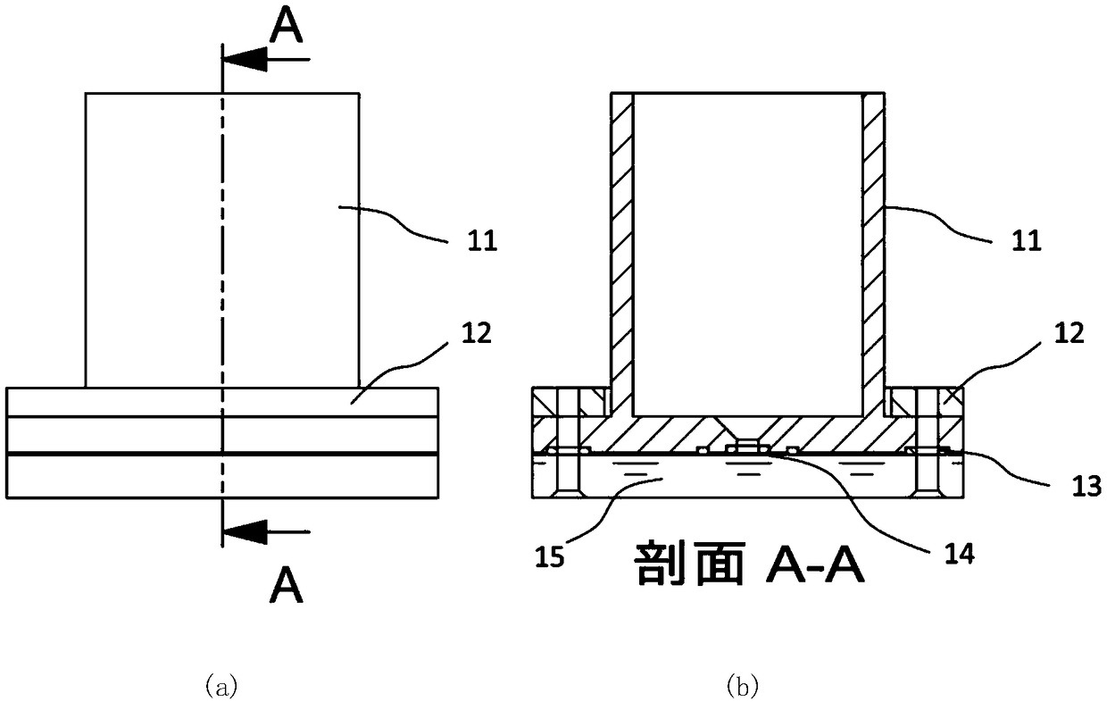
[0046] figure 1 It is a structural schematic diagram of the corrosion fixture of this embodiment. The figure (a) is a schematic diagram of the overall appearance, and the figure (b) is a cross-sectional view of the section A-A in the figure (a). The corrosion fixture includes a fixture upper part 11 , a pressure balance ring 12 , an O-ring set 13 and a glass slide 15 . figure 1 14 is the corroded chip.

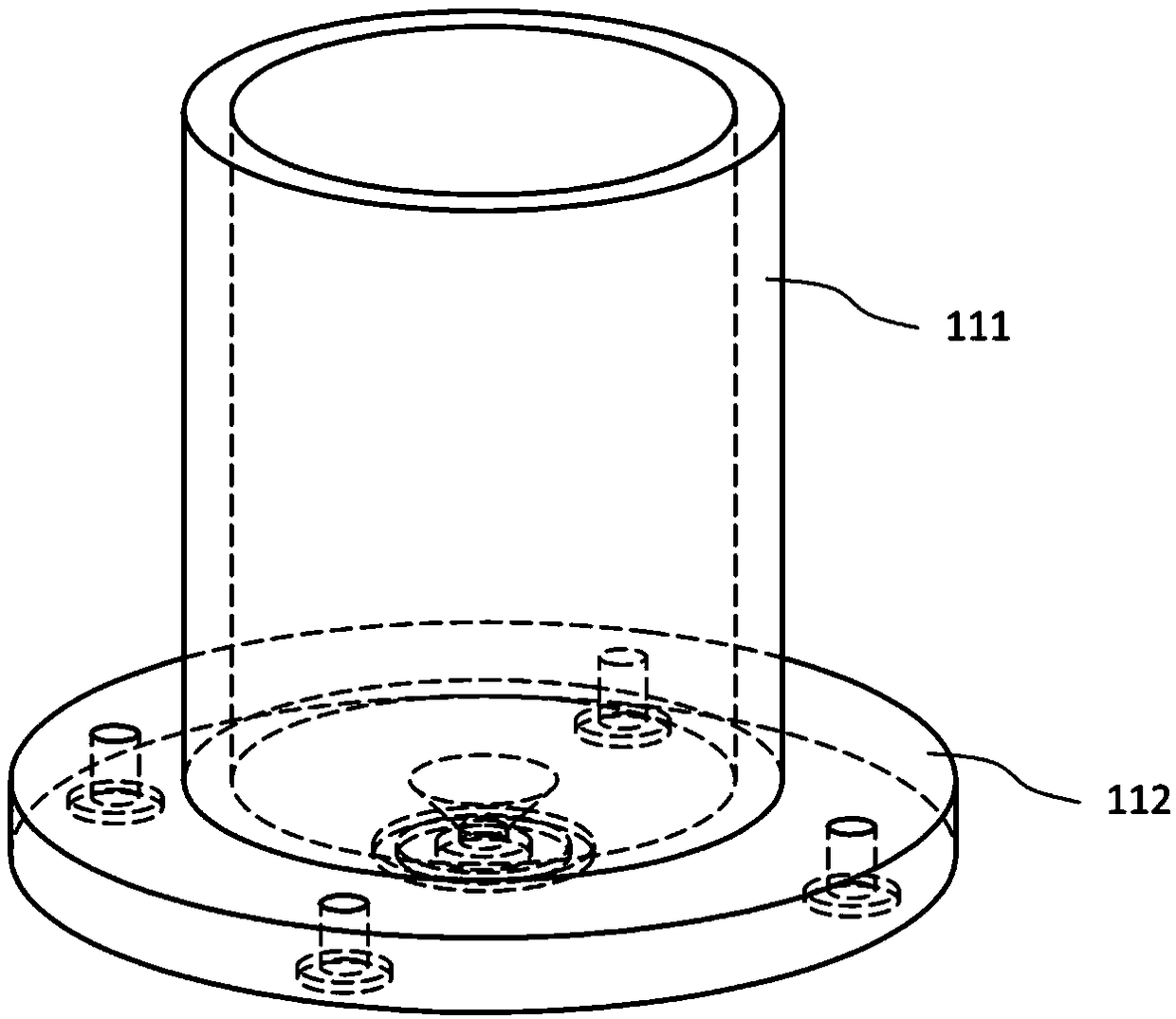
[0047] figure 2 It is a structural schematic diagram of the upper part 11 of the fixture. The upper part 11 of the jig is cylindrical and includes a tubular part 111 and a chassis 112, 111 and 112 are fixedly connected or integrally formed. The chassis 112 is provided with through holes, that is, screw holes (four screw holes are shown in the figure) around the chassis 112 for screw fixing. The tubular part 111 is used to contain the corrosion solution. A through hole is provided in the middle of the chassis 112 , that is, in the middle of the bottom of the upper part 1...

Embodiment 2

[0063] The difference between this embodiment and Embodiment 1 is that the pressure balance ring 12 in Embodiment 1 is removed, and the glass slide 15 and the upper part 11 of the fixture are directly fixed together. With this solution, although the pressure of the screw is not as uniform as in Example 1, the purpose of corrosion can be better achieved.

Embodiment 3

[0065] The difference between this embodiment and Embodiment 1 is that the glass slide 15 is replaced by a non-transparent slide. With this solution, although the light transmission of the slide cannot be used to realize the end point detection, other methods can be used to detect whether the corrosion is complete, such as by timing.


PUM


Abstract

The invention relates to a fixture and an etching method for one-sided area etching. The fixture comprises an upper part of the fixture, an upper end of the fixture is open, and a bottom part is provided with a through hole; A slide is positioned below the upper part of the jig; An O-ring group positioned between the upper part of the jig and the carrier sheet and positioned below the through hole; The O-ring group comprises an outer O-ring for preventing the external water bath solution from entering and an inner O-ring for placing an etched chip inside the O-ring group and preventing the etching liquid from etching out; A clamping device for clamping the upper part of the clamping device and the carrier sheet. Further may include a pressure balancing ring, a magnetic rotor, a surface protective film, and the like. The invention realizes the single-side corrosion facing upward, facilitates the discharge of corrosion gas, can carry out reliable corrosion on part of the single-side areaof the chip, protects other areas from being affected, and can be stable and reliable under the condition of corrosion penetration.

Description

technical field [0001] The invention belongs to the field of corrosion fixtures, and in particular relates to a stable and reliable corrosion fixing fixture for reliably corroding a partial area of ​​a single side of a chip, protecting other areas from being affected, and corrosion penetration conditions, and an etching method using the fixture. Background technique [0002] Wet etching of semiconductor chips is an indispensable basic process in microelectronics technology. Among them, wet etching of bulk silicon materials on chip substrates is one of the commonly used methods in MEMS technology. released from the silicon substrate. Etching includes etching the surface material and releasing the structure on the other side of the chip by etching through. In the field of scientific research, transparent nanoscale thin film materials can be obtained by using corrosion breakthrough release films, which is convenient for studying the mechanical, optical, and electronic properti...

Claims


Application Information

Patent Timeline
Patent Type & Authority Applications(China)
IPC IPC(8): H01L21/687H01L21/306
CPCH01L21/68778H01L21/30604H01L21/68785
Inventor 李志宏于博成孙梅陈清
Owner PEKING UNIV
Why Eureka
Try Eureka