
A rear-mounted electric spindle structure with braking function

A brake function and tail-mounted technology, which is applied in the field of tail-mounted electric spindle structure, can solve the problems of large space occupation, complex mechanical structure, and large heat generation, and achieve the effects of preventing signal interference, good control effect, and improving stability

Pending Publication Date: 2019-01-18
东莞司母戊精密科技有限公司
View PDF0 Cites 3 Cited by
  • Summary
  • Abstract
  • Description
  • Claims
  • Application Information

AI Technical Summary

Problems solved by technology

[0002] With the advancement of science and technology, the development of machine tool spindles is getting faster and faster, including three methods. The first is the traditional mechanical spindle, but it has the following disadvantages: 1. The mechanical structure is complex and takes up a lot of space; 2. The vibration is large, Low precision; 3. The kinetic energy loss of the belt-type mechanical transmission structure is large, and the energy consumption is high; 4. The torque of the asynchronous motor is small, and it is impossible to achieve low speed and large feed
The second type is the built-in electric spindle, which has the following disadvantages: 1. The built-in structure of the stator and rotor is complicated, and the manufacturing cost is high; 2. It is difficult to seal, the heat is large, and the heat dissipation is difficult; 3. High speed and low torque, the scope of application is small , large industry restrictions
Therefore, the structure of the tail-mounted electric spindle is preferred, but today's rear-mounted electric spindle still has the following disadvantages: 1. The position where the encoder is installed is susceptible to signal interference, which affects its function; 2. After the motor stops rotating, the spindle produces a large inertia , so that it cannot brake quickly, which makes it extremely inconvenient to use, and it is easy to cause accidents. In addition, the spindle needs to be stopped precisely so that when the machine tool enters compound processing, the spindle without locking cannot complete precise processing; 3. Use and built-in electric The same oil-cooled and water-cooled structure of the spindle increases the cost of use; therefore, it needs to be improved

Method used


Image

  • A rear-mounted electric spindle structure with braking function
  • A rear-mounted electric spindle structure with braking function
  • A rear-mounted electric spindle structure with braking function

Examples


Embodiment Construction

[0023] The present invention will be further described below in conjunction with accompanying drawing:

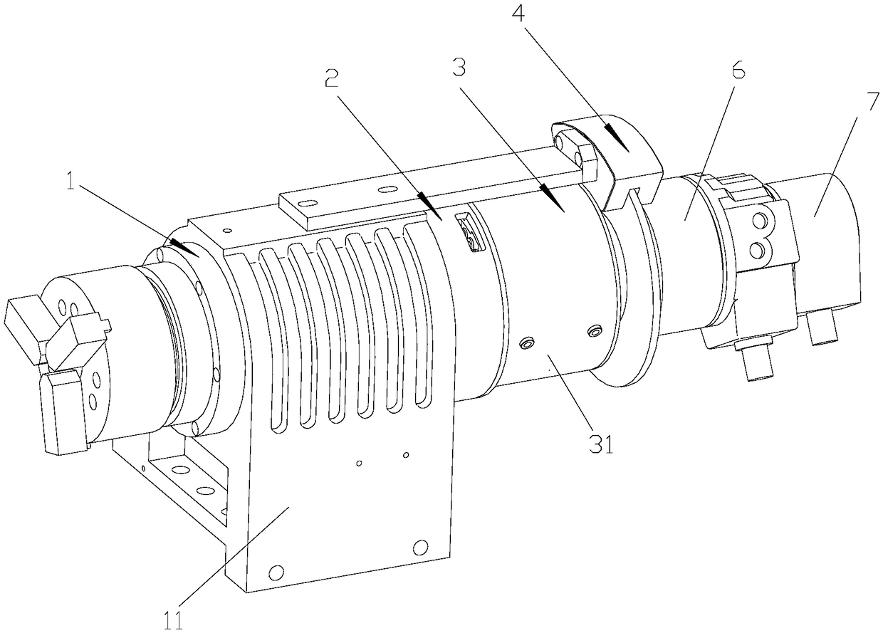
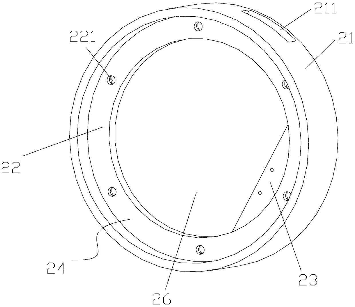
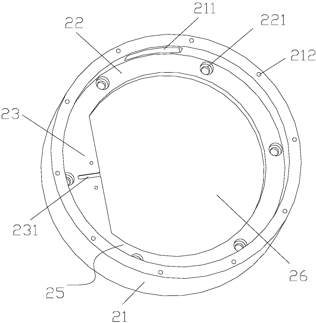
[0024] Such as Figure 1-6 As shown, a tail-mounted electric spindle structure with a braking function includes a mechanical spindle assembly 1, a flange 2, and a rear-mounted motor 3; the mechanical spindle assembly 1 is fixedly connected to the rear-mounted motor 3 through the flange 2, It also includes a braking device 4; an encoder mounting position 23 is provided in the flange 2; a slot 231 for hiding the encoder 5 wiring is provided on the encoder mounting position 23; An encoder 5 is installed; the braking device 4 has the functions of releasing, semi-braking and braking the main shaft 12 on the mechanical main shaft assembly 1 .

[0025] The flange plate 2 includes a circular flange housing 21 and a protruding ring 22 arranged inside the flange housing 21; the mounting position is arranged on the protruding ring 22 to form a "D"-shaped through hole with the protrud...


PUM


Abstract

The invention provides a rear-mounted electric spindle structure with a braking function, which comprises a mechanical spindle assembly, a flange and a rear-mounted motor. The mechanical spindle assembly is fixedly connected with a rear motor through a flange, and further comprises a brake device. The flange is provided with an encoder mounting position; The encoder mounting position is provided with a slot position for concealing the encoder traces; The encoder is mounted on the encoder mounting position. The brake device has the functions of releasing, half braking and braking the main shafton the mechanical main shaft assembly; The invention can effectively reduce the signal interference problem received by the encoder and has the advantages of quick braking with a brake device and high stability.

Description

technical field [0001] The invention relates to the field of electric spindle structures, in particular to a tail-mounted electric spindle structure with a braking function. Background technique [0002] With the advancement of science and technology, the development of machine tool spindles is getting faster and faster, including three methods. The first is the traditional mechanical spindle, but it has the following disadvantages: 1. The mechanical structure is complex and takes up a lot of space; 2. The vibration is large, Low precision; 3. The belt-type mechanical transmission structure has a large kinetic energy loss and high energy consumption; 4. The torque of the asynchronous motor is small, and it is impossible to achieve low speed and large feed. The second type is the built-in electric spindle, which has the following disadvantages: 1. The built-in structure of the stator and rotor is complicated, and the manufacturing cost is high; 2. It is difficult to seal, the...

Claims


Application Information

Patent Timeline
Patent Type & Authority Applications(China)
IPC IPC(8): H02K7/00H02K11/20F16D65/12F16D53/00
CPCH02K7/003H02K11/20F16D53/00F16D65/12
Inventor 郑金胜
Owner 东莞司母戊精密科技有限公司
Learn More