Optical element coating device and coating method

A technology of optical components and coating devices, which is applied in the field of thin film optical preparation and optical equipment, can solve the problems that the coating machine cannot place baffles, etc., and achieve the effects of improving scientific research and production efficiency, reducing the number of experiments, and expanding the scope of use

Active Publication Date: 2019-01-22
BEIJING RES INST OF SPATIAL MECHANICAL & ELECTRICAL TECH
View PDF7 Cites 2 Cited by
  • Summary
  • Abstract
  • Description
  • Claims
  • Application Information

AI Technical Summary

Problems solved by technology

[0006] The technical problem to be solved by the present invention is to overcome the deficiencies of the prior art and propose a coating device and coating method for optical elements. The device places a compensating baffle between the two evaporation sources to simultaneously correct the two evaporation sources The thickness of the film layer is uniform. The baffle does not need to be raised or dropped after being placed, and there will be no problems such as mechanism jamming or uniformity interference. At the same time, it solves the problem that some coating machines cannot be placed on both sides of the evaporation source. bezel problem

Method used


Image

  • Optical element coating device and coating method
  • Optical element coating device and coating method
  • Optical element coating device and coating method

Examples


Embodiment

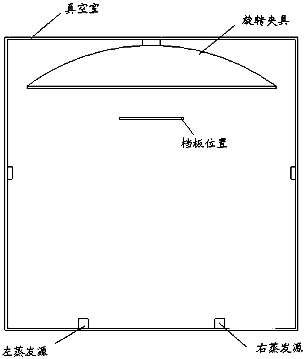
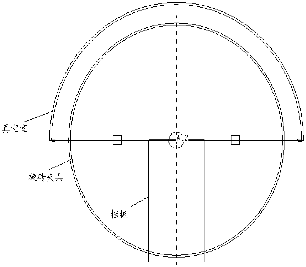
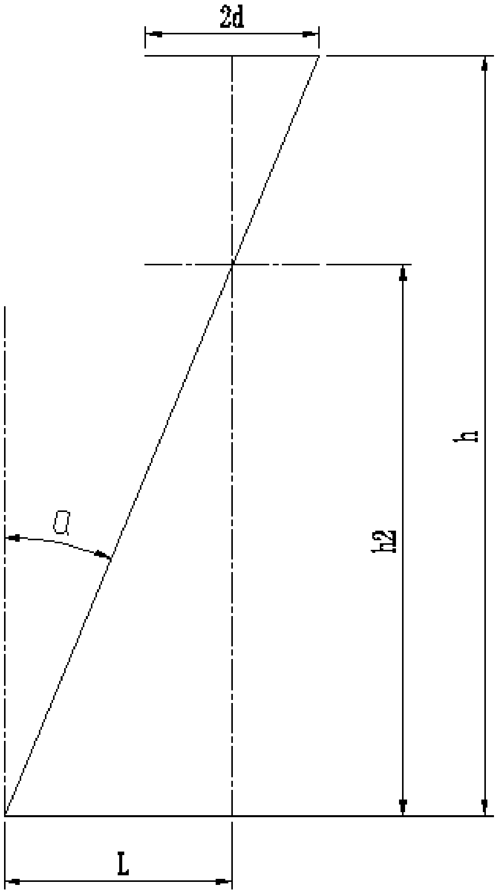
[0070] Such as Figure 1-4 As shown, a coating device for an optical element, the coating device includes a coating machine and a baffle; the coating machine includes a vacuum chamber, a left evaporation source, a right evaporation source and a fixture, and the left evaporation source and the right evaporation source are placed in the vacuum chamber At the bottom, the fixture is fixedly installed on the top of the vacuum chamber, the baffle is placed in the vacuum chamber of the coating machine, and the distance between the center of the baffle and the center of the left evaporation source is the same as that of the center of the right evaporation source; the fixture is used for coating and the distance between the center of the left evaporation source and the center of the bottom end of the vacuum chamber is L=1150mm, the distance between the center of the right evaporation source and the center of the bottom end of the vacuum chamber is L=1150mm; the maximum evaporation of th...


PUM

PropertyMeasurementUnit
thicknessaaaaaaaaaa

Abstract

The invention relates to an optical element coating device and coating method, and belongs to the technical field of optical equipment. The optical element coating device and coating method can be applied to the technical field of film optic preparation. According to the method, a metal material is used for designing a film thickness uniformity compensation device, the film thickness uniformity compensation device is placed at a center position, of a certain height, between two evaporator sources, in a coating process, a baffle state is not changed, the film thickness of the two evaporator sources can be amended at the same time, and the evenness of the two evaporator sources are not interfered mutually.

Description

technical field [0001] The invention relates to a film coating device and a film coating method of an optical element, which belong to the technical field of optical equipment and can be applied to the technical field of thin film optical preparation. Background technique [0002] Optical components are important components used in optical systems. Since each optical system has different requirements for the spectrum, it is necessary to coat the optical components. [0003] In the prior art, the optical element is placed on the spherical rotating fixture in the vacuum chamber of the coating machine, and the thin film material is placed in the evaporation source. After heating and evaporation, the thin film material forms a circular envelope surface within a certain evaporation angle and rises to the optical element. Form a film of a certain thickness. Since the thickness of the film deposited at each position where the evaporation envelope reaches the fixture is different, ...

Claims


Application Information

Patent Timeline
Patent Type & Authority Applications(China)
IPC IPC(8): C23C14/24
CPCC23C14/24
Inventor 王刚白云立周于鸣李昂王培培王利陈序张继友肖正航
Owner BEIJING RES INST OF SPATIAL MECHANICAL & ELECTRICAL TECH
Why Eureka
Try Eureka