Rail anti-torsion limit rail lower pad plate used for a fastening system

A technology of under-rail pads and limit baffles, which is applied in the field of rail transit, can solve problems such as long-term train running threats, deterioration of the environment along the line, and impact on ride comfort, so as to eliminate hidden dangers of train operation, reduce noise and environmental pollution. Noise pollution, simple structure effect

Pending Publication Date: 2019-01-22
洛阳双瑞橡塑科技有限公司
View PDF0 Cites 0 Cited by
  • Summary
  • Abstract
  • Description
  • Claims
  • Application Information

AI Technical Summary

Problems solved by technology

[0003] Even so, due to the high dynamic force and high stress of the operating load, and the rail is in a suspended state, the rail foot lacks restraint, the rail moves laterally, the rail foot twists, and the floating rail fastener will still cause the rail torsion and the rail torsion during the operation of the train. The inaccuracy of the bottom slope, after the long-term operation of the train, the torsion of the rail causes the relative sliding of the rail head in the lateral direction and the wheel in the axial direction, causing wave wear of the rail at a specific frequency, and the wave wear of the rail leads to a special noise - Corrugation noise, which is 3-15dB larger than normal rolling noise, which seriously affects people's riding comfort, endangers the health of passengers, deteriorates the environment along the line, and poses a great threat to the long-term operation of trains

Method used


Image

  • Rail anti-torsion limit rail lower pad plate used for a fastening system
  • Rail anti-torsion limit rail lower pad plate used for a fastening system
  • Rail anti-torsion limit rail lower pad plate used for a fastening system

Examples


Embodiment 1

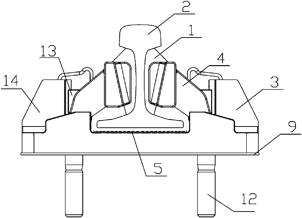
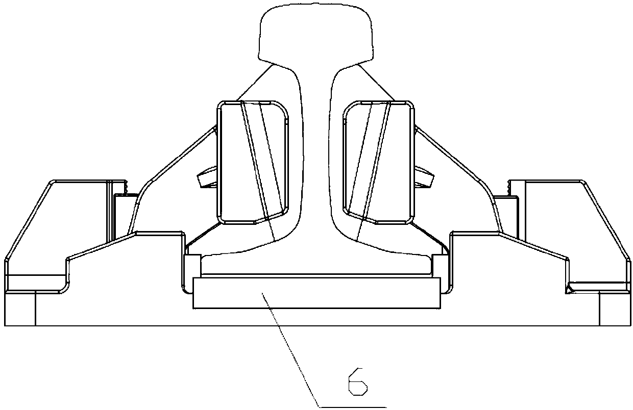
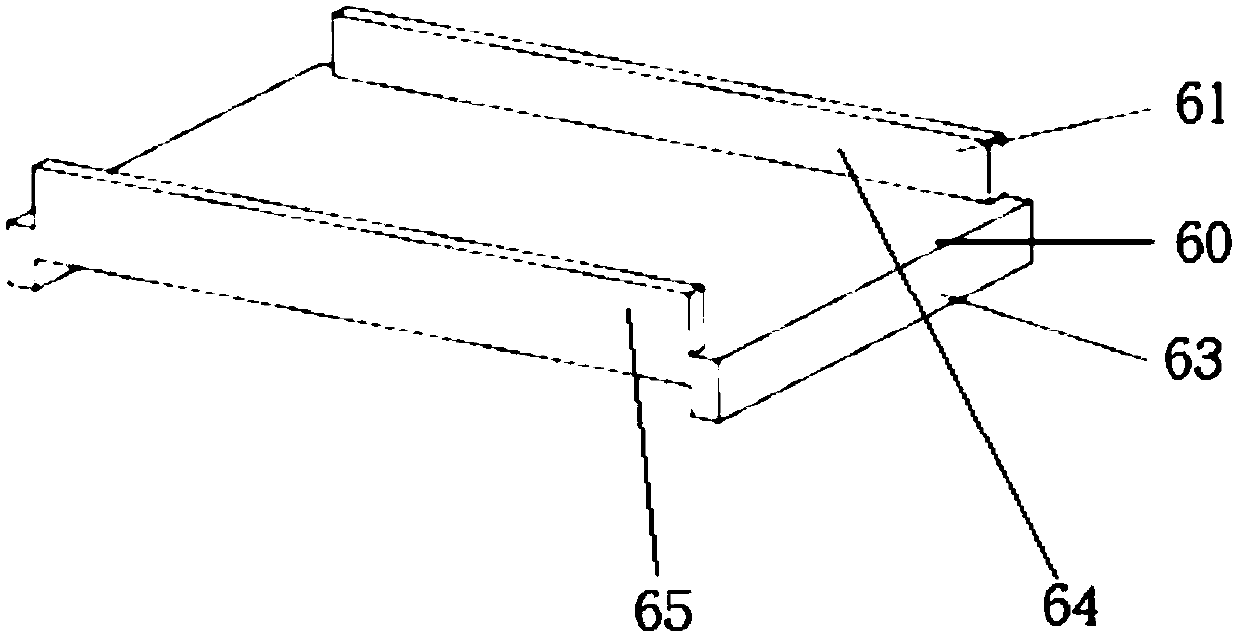
[0038] Such as figure 2 , the present invention provides an under-rail backing plate 6, the under-rail backing plate 6 replaces the anti-collision backing plate 5 in the prior art and is installed between the rail 2 and the bottom plate 3. Such as image 3 As shown, the under-rail backing plate 6 includes a base plate 60 , and the base plate 60 is rectangular. A group of opposite side edges of the base plate 60 is provided with a limit protrusion 61, and the limit protrusion 61 is perpendicular to the base plate 60; another set of opposite side edges is provided with a positioning protrusion 63 perpendicular to the base plate 60; The protruding directions of the positioning protrusions 61 and the positioning protrusions 63 relative to the substrate 60 are opposite. The base plate 60 and the limiting protrusion 61 form a groove-shaped structure, and accommodate the rail foot of the steel rail 2 in the groove-shaped structure. The side of the position-limiting protrusion 61 ...

Embodiment 2

[0046] The second embodiment mainly describes the embodiment of the structure of the under-rail backing plate 6 which is vulcanized by steel plate and rubber.

[0047] Such as Figure 4-Figure 6 , the substrate 60 is vulcanized by steel plate and rubber, and the substrate 60 includes three layers, wherein the upper layer 601 and the lower layer 603 are rubber, and the middle layer 602 is steel plate. Limiting protrusion 61 is also vulcanized by steel plate and rubber. Such as Figure 4-Figure 5 , the position-limiting protrusion 61 is set as two layers, the inner layer 612 is a steel plate, and the outer layer 611 is rubber. As a whole, the overall strength of the substrate 60 and the position-limiting protrusion 61 is enhanced; or the inner layer 612 is rubber, and the outer layer 611 is a steel plate. Preferably, the inner layer 612 and the outer layer 611 of the position-limiting protrusion 61 are respectively connected to the The upper layer 601 and the middle layer 602...

Embodiment 3

[0053] The third embodiment mainly describes the structure of the limit block 31 on the bottom plate 3 . Such as Figure 17-21 , the middle area of ​​the bottom plate 3 is provided with a recessed portion, and a limit block 31 is provided near a pair of opposite sides of the recessed portion perpendicular to the rail direction. Such as Figure 17 and Figure 19 , keeping a certain distance from the edge of the recessed part, a limit block 31 is set on the bottom plate 3, and the stop block 31 can be a wedge-shaped block or a strip block; the limit block 31 is adjacent to the edge of the recessed part The second inner side 311 is perpendicular to the bottom plate 3 and parallel to the edge of the adjacent recessed portion. Such as Figure 18 , the second inner surface of the limiting block 31 is perpendicular to the bottom plate 3 , and the limiting block 31 shares a side wall with the adjacent recessed portion. Such as Figure 20 , for the fastener system with shoulders,...


PUM


Abstract

The invention discloses a rail anti-torsion limit rail lower pad plate used for a fastening system. The fastening system comprises a rail (2), a bottom plate (3) and a rail lower pad plate (6). The rail lower pad plate (6) is positioned between the bottom plate (3) and the rail. The bottom plate is provided with a finite position piece. The lower rail pad plate comprises a base plate (60), whereinthe base plate comprises a set of mutually parallel opposite sides, wherein the mutually parallel opposite sides are provided with stopping protrusions (61) perpendicular to the base plate, and the stopping protrusions and the base plate form a groove structure. The limiting protrusion (61) is positioned between the rail pin and the bottom plate limiting member. The invention effectively reducesor even eliminates the lateral movement and torsional oscillation of the rail, so as to reduce or even eliminate the generation of the rail corrugation, reduce the noise and the environmental sound pollution, improve the ride comfort and eliminate the hidden trouble of the train operation. At the same time, the characteristics of simple structure and convenient installation and adjustment of the fastener system are retained, which is very suitable for ballastless and ballasted track lines.

Description

technical field [0001] The invention belongs to the technical field of rail transit, and specifically provides a rail torsion-resistant under-rail backing plate for a fastener system. Background technique [0002] Floating rail fastener is a new type of vibration and noise reduction rail fastener system. The fastener system uses elastic wedge support to support the lower jaw of the rail head, so that the bottom of the rail is separated from the bearing seat, and the rubber elastic block used as an elastic support Then it is supported and positioned by the supporting side plate fixed on the foundation under the rail. Each fastener node of the floating rail fastener system is supported by a cast iron base, two cast iron support side plate brackets, two cast iron wedge block fixings, two rubber elastic block elastic wedge rail supports, and a safety bearing rubber under the rail Pad and two spring clips. Under normal circumstances, the safety bearing rubber pad does not conta...

Claims


Application Information

Patent Timeline
Patent Type & Authority Applications(China)
IPC IPC(8): E01B9/68
CPCE01B9/683E01B9/688
Inventor 闫作为曾飞李强段勇奇王彦飞
Owner 洛阳双瑞橡塑科技有限公司
Why Eureka
Try Eureka