Form-variable stilling basin front end energy dissipation structure and energy dissipation method thereof

A stilling tank and pressure sensor technology, applied in water conservancy projects, sea area engineering, coastline protection, etc., can solve the problems of low energy dissipation efficiency and high pressure of stilling tanks, improve atomization and reduce various pressures , the effect of stable water flow out of the pool

Active Publication Date: 2019-01-22
KUNMING UNIV OF SCI & TECH
View PDF3 Cites 3 Cited by
  • Summary
  • Abstract
  • Description
  • Claims
  • Application Information

AI Technical Summary

Problems solved by technology

[0007] Aiming at the problems of excessive pressure of various types of pressure on the front bottom plate of the stilling tank and low energy dissipation efficiency of the stilling tank in the current dischar

Method used


Image

  • Form-variable stilling basin front end energy dissipation structure and energy dissipation method thereof
  • Form-variable stilling basin front end energy dissipation structure and energy dissipation method thereof
  • Form-variable stilling basin front end energy dissipation structure and energy dissipation method thereof

Examples


Embodiment 1

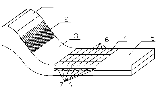
[0038] Embodiment 1: as figure 1 , 7 , 8 and 9, a modified form of stilling pool front end energy dissipation structure, including WES curve section 1, WES step straight section 2, WES anti-arc section 3, stilling pool front end 4, stilling pool rear end 5, Pressure sensor, controller, auxiliary hydraulic jacking device, main hydraulic jacking device, WES curve section 1 is connected with WES straight section 2, WES straight section 2 is connected with WES anti-arc section 3, the tail of WES anti-arc section 3 is connected with the disappearing The front end 4 of the stilling pool is connected, and the front end 4 of the stilling pool is connected with the rear end 5 of the stilling pool. The front end 4 of the stilling pool is evenly divided into several blocks 6, and each block 6 is equipped with an auxiliary hydraulic jack Lifting device, auxiliary hydraulic jacking device includes auxiliary hydraulic cylinder 7-5, auxiliary lifting column 7-6, auxiliary hydraulic cylinder...

Embodiment 2

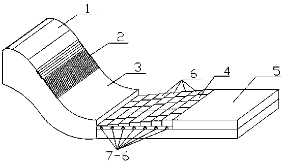
[0047] Embodiment 2: as figure 2 As shown, the structure of this embodiment is the same as that of Embodiment 1, the difference is that the first row of blocks 6 at the front end 4 of the stilling pool all descends as a whole, and the descending height is the same and the largest, and every subsequent row descends, and the descending height Although it is consistent but gradually decreases, a drop sill with a certain height difference can be formed between the WES anti-arc section 3 and the front end 4 of the stilling pool, and the front end 4 of the stilling pool can be formed as a whole to form a bottom slope of the stilling pool i>0 This form can increase the concentration of aeration in the process of underflow energy dissipation, and strengthen the tumbling of the water flow at the connection, so as to achieve the purpose of energy dissipation.

Embodiment 3

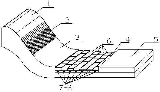
[0048] Embodiment 3: as image 3 As shown, the structure of this embodiment is the same as that of Embodiment 1, the difference is that the relative height H of the first row of blocks 6 at the front end 4 of the stilling pool does not change, and the overall height H of each row of blocks 6 afterward All descend, the relative height H of the same row of blocks is equal, and the height of the blocks 6 of different rows gradually increases as they go further, so that the front end 4 of the stilling pool can form a bottom slope of the stilling pool as a whole i< 0, so that the discharged water can continuously fall at the front end 4 of the stilling basin, and more sufficient collision and mixing can be carried out at the position between the front end 4 of the stilling basin and the rear end 5 of the stilling basin It is more conducive to the energy dissipation of the water flow in the stilling pool.


PUM


Abstract

The invention relates to a form-variable stilling basin front end energy dissipation structure and an energy dissipation method thereof. The form-variable stilling basin front end energy dissipation structure is mainly composed of a WES overflow weir and a stilling basin, wherein the WES overflow weir comprises a curve section of the WES overflow weir, a linear section of the WES overflow weir andan inverted arc section of the WES overflow weir; the stilling basin comprises a stilling basin front end, a stilling basin rear end and other parts. Innovation is conducted mainly aiming to high intensity of pressure of the stilling basin front end, the stilling basin front end is divided into blocks with same size, and accessory hydraulic jacking devices are arranged on the stilling basin bottom plate blocks obtained through dividing respectively; the relative height between each stilling basin bottom plate block and the inverted arc section of the WES overflow weir is adjusted through accessory hydraulic control valves; in order to bring convenience to actual management of engineering, a main hydraulic control valve is installed, and the whole device can be adjusted.

Description

technical field [0001] The invention relates to a modified form stilling pool front end energy dissipation structure and an energy dissipation method thereof, belonging to the field of flood discharge and energy dissipation of hydraulic structures in water conservancy and hydropower projects. Background technique [0002] In the design of dam engineering, flood discharge and energy dissipation are the two major tasks undertaken by the discharge structure, that is, to safely discharge excess flood water while strictly controlling the erosion of the dam body and downstream foundation pit by the discharge flow to prevent damage to the dam body and instability of the dam foundation . Especially for flood discharge projects with high water head and large flow, there are problems such as large flow velocity and pulsating pressure at the bottom of the bottom plate, high difficulty in anti-shock protection, large size of stilling basin required, and high cost. Therefore, research on...

Claims


Application Information

Patent Timeline
IPC IPC(8): E02B8/06
CPCE02B8/06
Inventor 杨具瑞汤建青郭莹莹任中成陈卫星
Owner KUNMING UNIV OF SCI & TECH
Why Eureka
Try Eureka