
Gravity switching unit and aircraft engine inverted flight oil supply and ventilation device comprising same

An aero-engine and switching unit technology, applied in the directions of engine components, engine lubrication, turbine/propulsion lubrication, etc., can solve the problems of inconvenient disassembly, poor maintenance, large volume and weight of hydraulic accumulators, etc. The effect of maintenance, low weight and simple structure

Pending Publication Date: 2019-01-22
重庆天骄航空动力有限公司
View PDF7 Cites 1 Cited by
  • Summary
  • Abstract
  • Description
  • Claims
  • Application Information

AI Technical Summary

Problems solved by technology

This method can be used for engines that do not require a large amount of lubricating oil supply, but for turboprop engines, a large amount of lubricating oil is required to be input into the propeller control system as the working fluid. If the hydraulic pressure accumulator is used, its volume needs to reach several Ten liters can meet the requirements, resulting in huge volume and weight of the hydraulic pressure accumulator
The gas connection in the lubricating oil tank uses a separate valve to ensure the gas communication between the centrifugal ventilator and the lubricating oil tank during inverted flight, but this device is installed inside the lubricating oil tank, which is poor in maintainability and inconvenient to disassemble

Method used


Image

  • Gravity switching unit and aircraft engine inverted flight oil supply and ventilation device comprising same
  • Gravity switching unit and aircraft engine inverted flight oil supply and ventilation device comprising same
  • Gravity switching unit and aircraft engine inverted flight oil supply and ventilation device comprising same

Examples


Embodiment Construction

[0026] The specific implementation manners of the present invention will be further described in detail below in conjunction with the accompanying drawings.

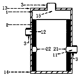
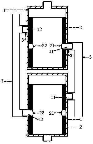
[0027] see figure 1 , the gravity switching unit of a specific embodiment, the casing 1, the casing 1 is a vertical hollow straight cylinder, the gravity switching cylinder 2 can be vertically slid inside the casing 1, the gravity switching cylinder The body 2 is also a vertical hollow straight cylinder; the outer wall of the gravity switching cylinder 2 corresponds to the inner wall of the housing 1, and the height of the gravity switching cylinder 2 is smaller than the height of the housing 1; A through hole I11 and a second through hole I12, a first through hole II21 and a second through hole II22 are respectively opened on the wall of the gravity switching cylinder 2, the first through hole I11 and the first through hole II21 are located in the same vertical On the plane and the distance from the first through hole ...


PUM


Abstract

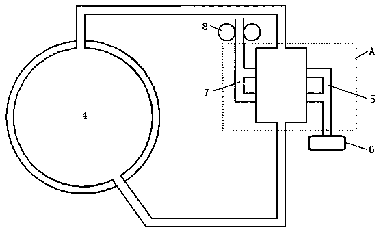
The invention relates to a gravity switching unit and an aircraft engine inverted flight oil supply and ventilation device comprising the same. The oil supply and ventilation device comprises two gravity switching units and a lubricating oil box, wherein each gravity switching unit comprises a shell; a gravity switching barrel is in vertical sliding cooperation in the shell; the wall of the shellis provided with a first through hole I and a second through hole I; the wall of the gravity switching barrel is provided with a first through hole II and a second through hole II; the upper surface and the lower surface of the shell are respectively connected with a sealing plate; any one sealing plate is provided with a pipe connecting hole; the upper part and the lower part of the lubricating oil box are respectively connected with the pipe connecting holes of the gravity switching units; a through hole in communication with the shell of the gravity switching unit connected with the lower part of the lubricating oil box and a through hole that is misaligned to the shell of the gravity switching unit connected with the upper part of the lubricating oil box to be sealed are both connectedwith a booster pump through a lubricating oil conduit; another two through holes on two shells are both connected with a centrifugal ventilator through air conduits. According to the oil supply and ventilation device, the oil supply and the ventilation of the lubricating oil box can be simultaneously guaranteed.

Description

technical field [0001] The invention belongs to the technical field of lubricating engines in mechanical engineering, and in particular relates to a gravity switching unit and an aeroengine inverted fuel supply ventilation device containing the unit. Background technique [0002] Aircraft, especially military aircraft, have various flight attitude requirements, and the continuous flight capability in different flight attitudes poses a huge challenge to the stable operation of aviation gas turbine engines. [0003] For general aeroengines, when the engine is flying upside down, the oil output of the oil tank and the ventilation of the oil tank are in abnormal working conditions. Due to the attitude, the oil supply pipe at the bottom of the oil tank cannot deliver the oil to the booster. The pump is delivered to the lubricating parts through the booster pump. At this time, the lubricating oil supply to the lubricating parts of the engine is interrupted, and the long-term inver...

Claims


Application Information

Patent Timeline
Patent Type & Authority Applications(China)
IPC IPC(8): F02C7/06
CPCF02C7/06
Inventor 胡志鹏刘闯颜腾冲潘庆伟
Owner 重庆天骄航空动力有限公司
Learn More