Robotic greasing system

A robot and grease injection technology, which is applied in the direction of mechanical equipment, engine components, engine lubrication, etc., can solve the problems of large deviation of grease injection amount and grease injection position, uneven bearing lubrication, poor appearance quality, etc., and achieve improvement Production efficiency, reducing waste of raw materials, and improving product quality

Pending Publication Date: 2019-01-22
HARBIN BEARING GROUP CORP
View PDF0 Cites 5 Cited by
  • Summary
  • Abstract
  • Description
  • Claims
  • Application Information

AI Technical Summary

Problems solved by technology

[0004] The purpose of the present invention is to solve the problem of low efficiency of existing grease injection equipment, large deviation of grease injection amount and grease injection position, resulting in uneven lubrication of bearings, poor appearance quality, and wire drawing phenomenon after the grease injection is completed. problem, and then provide a robotic grease injection system

Method used


Image

  • Robotic greasing system
  • Robotic greasing system
  • Robotic greasing system

Examples


specific Embodiment approach 1

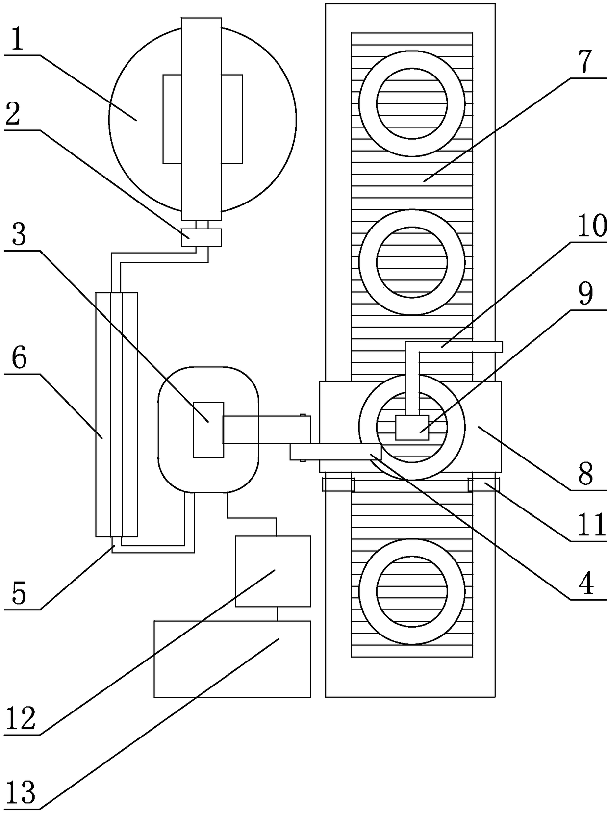
[0021] Specific implementation mode one: combine figure 1 Describe this embodiment, a robotic grease injection system of this embodiment, which includes a grease injection machine 1, a suction device 2, a grease injection robot 3, a grease injection working head 4, an oil pipeline 5, a gantry frame 6, a belt conveyor machine 7 and bearing fixture 8, the grease injection robot 3 is set on one side of the belt conveyor 7, the bearing fixture 8 is set on the belt conveyor 7, and the grease injection working head 4 is installed at the execution end of the grease injection robot 3, so The bearing fixture 8 is arranged opposite to the grease injection working head 4. The upper beam of the gantry 6 is provided with an oil delivery pipe installation groove along its length direction. The oil delivery pipeline 5 is installed on the upper beam of the gantry 6. One end of the oil delivery pipeline 5 is connected to the grease injection The oil outlet of the grease tank of the machine 1 i...

specific Embodiment approach 2

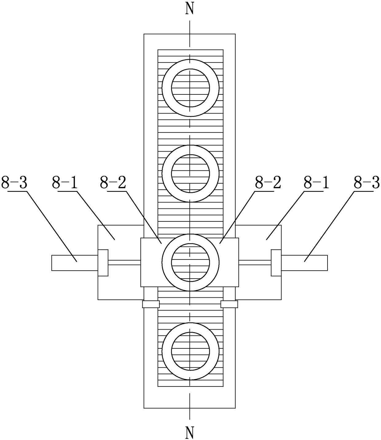
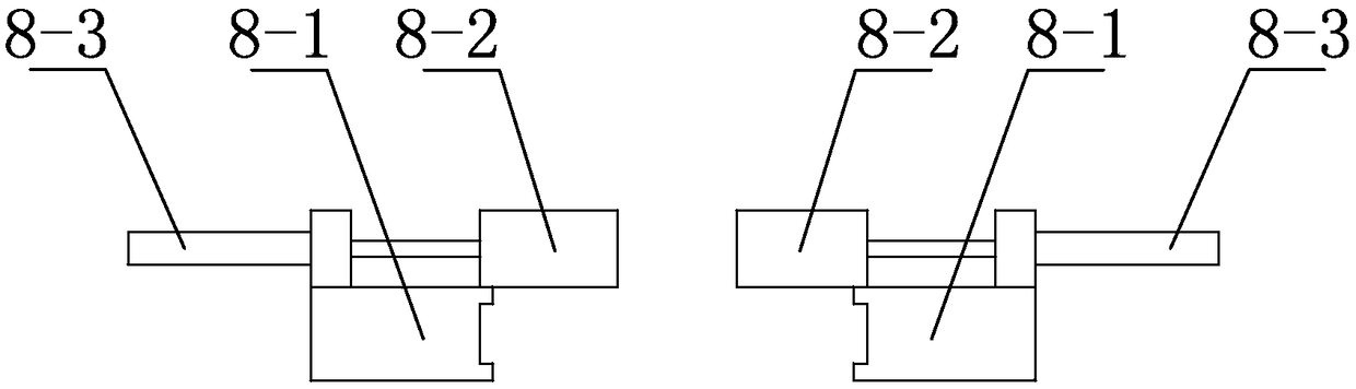
[0023] Specific implementation mode two: combination Figure 2 to Figure 4 To illustrate this embodiment, the bearing fixture 8 of this embodiment includes two clamping assemblies, and the two clamping assemblies are symmetrically arranged on both sides of the belt conveyor 7 along the centerline N-N of the belt conveyor 7, and each clamping assembly Including base 8-1, jaw 8-2, cylinder 8-3, base 8-1 is fixed on the frame side wall of belt conveyor 7, cylinder 8-3 is horizontally arranged on the upper end surface of base 8-1 , the piston rod of the cylinder 8-3 is affixed to the jaw 8-2. In this way, the bearing fixture 8 can accurately position the bearing, and the two clamping assemblies are arranged symmetrically on both sides of the belt conveyor 7. When the bearing is transported by the belt conveyor 7 to the station 3 of the grease injection robot, the two Cylinder 8-3 starts, and drives two jaws 8-2 to move to the middle and clamps and fixes the bearing. Other compos...

specific Embodiment approach 3

[0024] Specific implementation mode three: combination Figure 2 to Figure 4 To illustrate this embodiment, the end of the jaw 8-2 of this embodiment is processed with an arc-shaped groove matching the outer ring of the bearing. In this way, the jaw 8-2 adopts a conformal design to precisely position the bearing. Other compositions and connections are the same as those in Embodiment 1 or Embodiment 2.


PUM


Abstract

The invention relates to the technical field of machining, in particular to a robotic greasing system and solves the problems that existing greasing equipment has low efficiency, greasing quantity andgreasing position deviations are large, non-uniform bearing lubrication is caused, poor appearance quality is caused, and stringing occurs after greasing. A greasing robot is arranged on one side ofa belt conveyor; a bearing clamp is arranged on the belt conveyor; a greasing working head is mounted at the executing end of the greasing robot; the bearing clamp corresponds to the greasing workinghead in position; a grease pipeline mounting groove is arranged in an upper cross beam of a gantry along its length, a grease pipeline is mounted on the upper cross beam of the gantry, one end of thegrease pipeline is connected with a grease outlet of a grease box of a greasing unit, the other end of the grease pipeline is connected with a grease inlet of the greasing working head, and a suck-back device is arranged on one side of the grease pipeline close to the greasing unit. The robotic greasing system is applied to precise and continuous greasing production for grease lubricated bearings.

Description

technical field [0001] The invention relates to the technical field of mechanical processing, in particular to a robot grease injection system. Background technique [0002] At present, the market has high requirements for bearing quality and precision, and the bearing grease injection process directly affects the lubrication effect of the bearing, thus greatly affecting the service life of the bearing. The traditional grease injection process adopts the mold injection method, which is not only inefficient, but also has a large deviation in the amount of grease injected and the position of the grease injected, resulting in uneven lubrication of the bearing and poor appearance quality. Due to the high viscosity of the bearing grease, wire drawing will occur after the grease injection is completed, and it needs to be cleaned, which increases the post-processing steps. The traditional mode adopts manual operation and single-piece production for grease lubricated bearings. For ...

Claims


Application Information

Patent Timeline
Patent Type & Authority Applications(China)
IPC IPC(8): F16N7/00
CPCF16N7/00
Inventor 孟祥国岳靖凯张昊晟胡冰涛杨海峰管秀丽刘新红
Owner HARBIN BEARING GROUP CORP
Why Eureka
Try Eureka