Environment-friendly industrial waste gas purifying device and method
A technology of industrial waste gas and purification equipment, which is applied in the direction of chemical instruments and methods, separation methods, climate change adaptation, etc., can solve problems such as air pollution, achieve high purification efficiency, good purification effect, and prevent clogging
- Summary
- Abstract
- Description
- Claims
- Application Information
AI Technical Summary
Problems solved by technology
Method used
Image

Examples
specific Embodiment approach 1
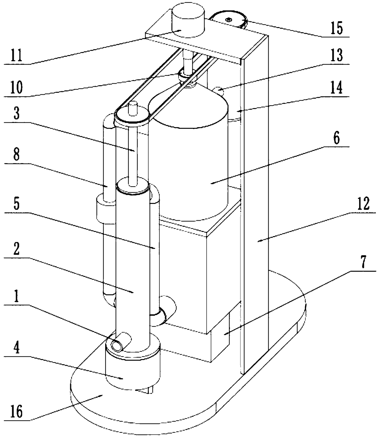
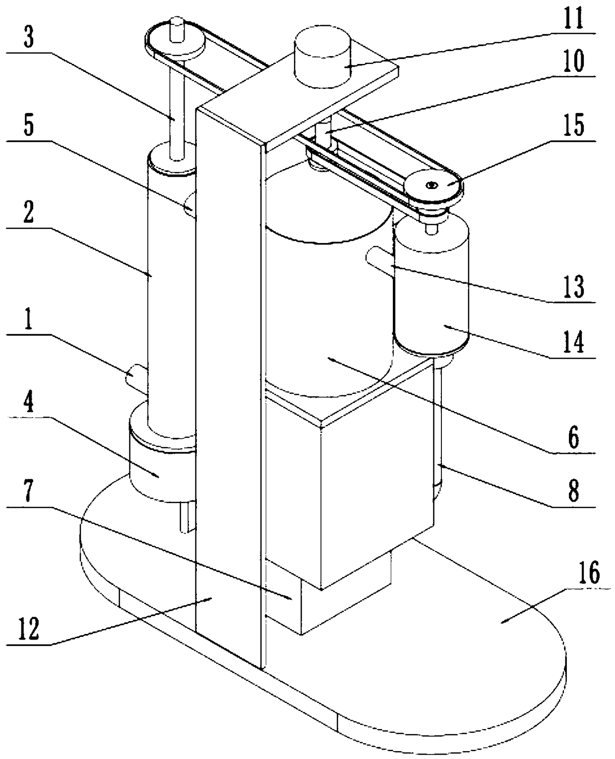
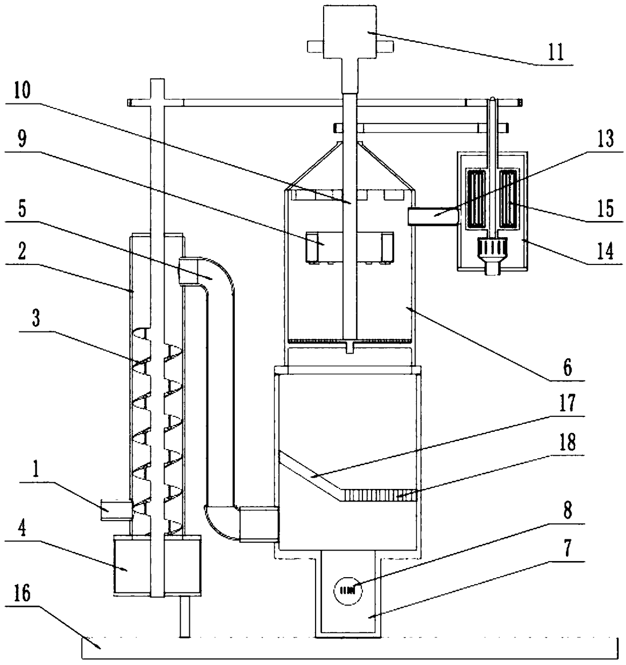
[0032] like Figure 1-11As shown, an environment-friendly industrial waste gas purification device includes an air intake pipe 1, an air intake primary filter cartridge 2, a primary filter dust fall assembly 3, a dust collection cylinder 4, a curved air delivery pipe 5, a spray reaction cylinder 6, and a liquid supply tank 7 , a water delivery pipe 8 with a circulating water pump, a spray box 9, a suction filter assembly 10, a drive assembly 11, a mounting frame 12, a direct air pipe 13, a rear filter cartridge 14, an adsorption dehumidification assembly 15 and a base plate 16, the The lower end of the air intake primary filter cartridge 2 is fixedly connected and communicated with the dust collection cylinder 4, and the dust collection cylinder 4 is fixedly connected on the base plate 16; On the top surface, the other end of the primary filter and dust collection assembly 3 is connected to the bottom surface of the dust collection tube 4 in rotation; One end of the curved ai...
specific Embodiment approach 2
[0033] Such as Figure 1-11 As shown, the drive assembly 11 includes a drive motor 11-1 and a drive shaft 11-2; the output end of the drive motor 11-1 is connected to the drive shaft 11-2 through a coupling, and the bottom end of the drive shaft 11-2 The suction filter assembly 10 is fixedly connected. When the drive assembly 11 is in use, the drive motor 11-1 can drive the drive shaft 11-2 to rotate around its own axis after the drive motor 11-1 is connected to the power supply, and the drive shaft 11-2 can drive the suction filter assembly 10 to work when the drive shaft 11-2 rotates.
specific Embodiment approach 3
[0034] Such as Figure 1-11 As shown, the suction filter assembly 10 includes a rotating shaft 10-1, a first sprocket 10-2, a suction fan 10-3, a rotating filter plate 10-4, a shaft frame plate 10-5 and a cleaning brush 10- 6; the bottom end of the drive shaft 11-2 is fixedly connected to the top of the rotating shaft 10-1; the upper end of the rotating shaft 10-1 is connected to the top of the spray reaction cylinder 6 in rotation, and the rotating shaft 10-1 From top to bottom, the first sprocket 10-2, the suction fan 10-3 and the rotating filter plate 10-4 are fixedly connected in turn, and the first sprocket 10-2 is located at the upper end of the spray reaction cylinder 6, and the air suction The fan 10-3 and the rotating filter plate 10-4 are rotatably connected to the inside of the spray reaction cylinder 6; the bottom end of the rotating shaft 10-1 is rotatably connected to the pedestal plate 10-5, and the pedestal plate 10- 5 is fixedly connected to the middle end of...
PUM
 Abstract
Description
Claims
Application Information
 - Generate Ideas
- Intellectual Property
- Life Sciences
- Materials
- Tech Scout
- Unparalleled Data Quality
- Higher Quality Content
- 60% Fewer Hallucinations
Browse by: Latest US Patents, China's latest patents, Technical Efficacy Thesaurus, Application Domain, Technology Topic, Popular Technical Reports.
© 2025 PatSnap. All rights reserved.Legal|Privacy policy|Modern Slavery Act Transparency Statement|Sitemap|About US| Contact US: help@patsnap.com