High-performance continuous forging and pressing device for alloy steel rods

An alloy steel bar, high-performance technology, applied in forging/pressing/hammer devices, operating devices, metal processing equipment, etc., can solve the problems of discontinuous forging process, low work efficiency, manual refueling, etc.

Active Publication Date: 2019-01-25
安徽震祥精工科技有限公司
View PDF5 Cites 4 Cited by
  • Summary
  • Abstract
  • Description
  • Claims
  • Application Information

AI Technical Summary

Problems solved by technology

[0002] High-performance alloys refer to advanced high-temperature alloy materials and metals produced by the production technology of civilian products. They have the advantages of high strength, high toughness, high conductivity, corrosion resistance, high wear resistance, and high (low) temperature resistance. High-performance alloy steel rods made of alloys are often used for rotating shafts or connecting shafts in machinery. Before assembly, high-performance alloy steel rods need to be forged at both ends of the steel rods into a flat or square shape, and then matched with other parts. The existing Forging equipment needs manual loading and clamping before forging, and manual refueling after forging, which makes the forging process discontinuous and low in work efficiency. Therefore, we propose a high-performance alloy steel bar continuous forging device to solve the above problems

Method used


Image

  • High-performance continuous forging and pressing device for alloy steel rods
  • High-performance continuous forging and pressing device for alloy steel rods
  • High-performance continuous forging and pressing device for alloy steel rods

Examples


Embodiment Construction

[0016] The following will clearly and completely describe the technical solutions in the embodiments of the present invention with reference to the accompanying drawings in the embodiments of the present invention. Obviously, the described embodiments are only some of the embodiments of the present invention, not all of them. Based on the embodiments of the present invention, all other embodiments obtained by persons of ordinary skill in the art without making creative efforts belong to the protection scope of the present invention.

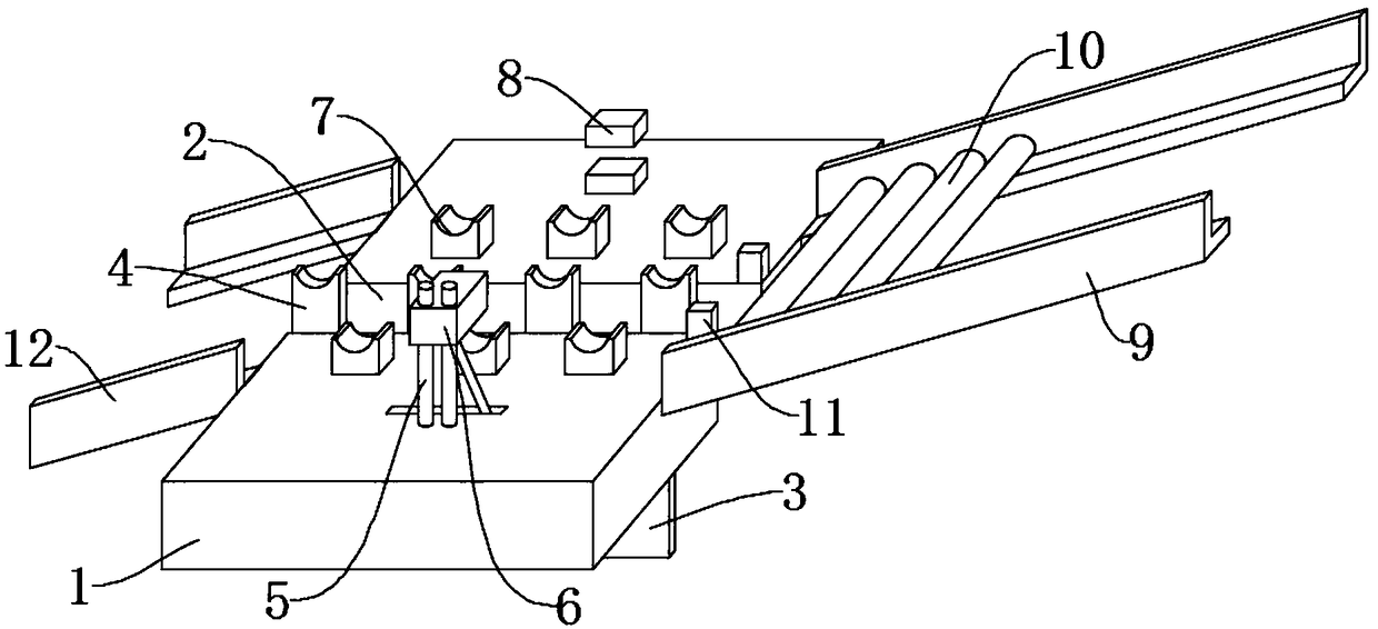
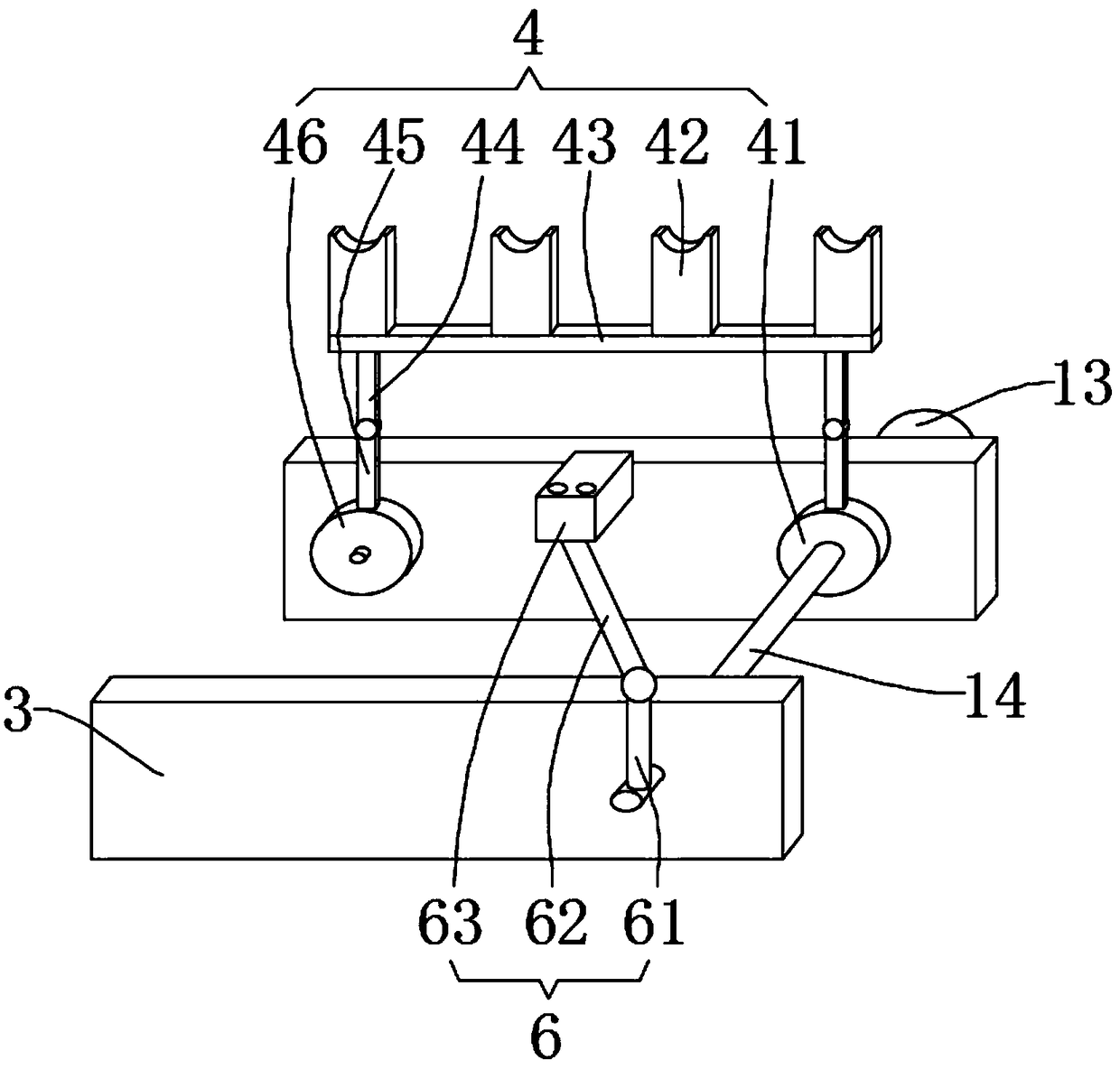
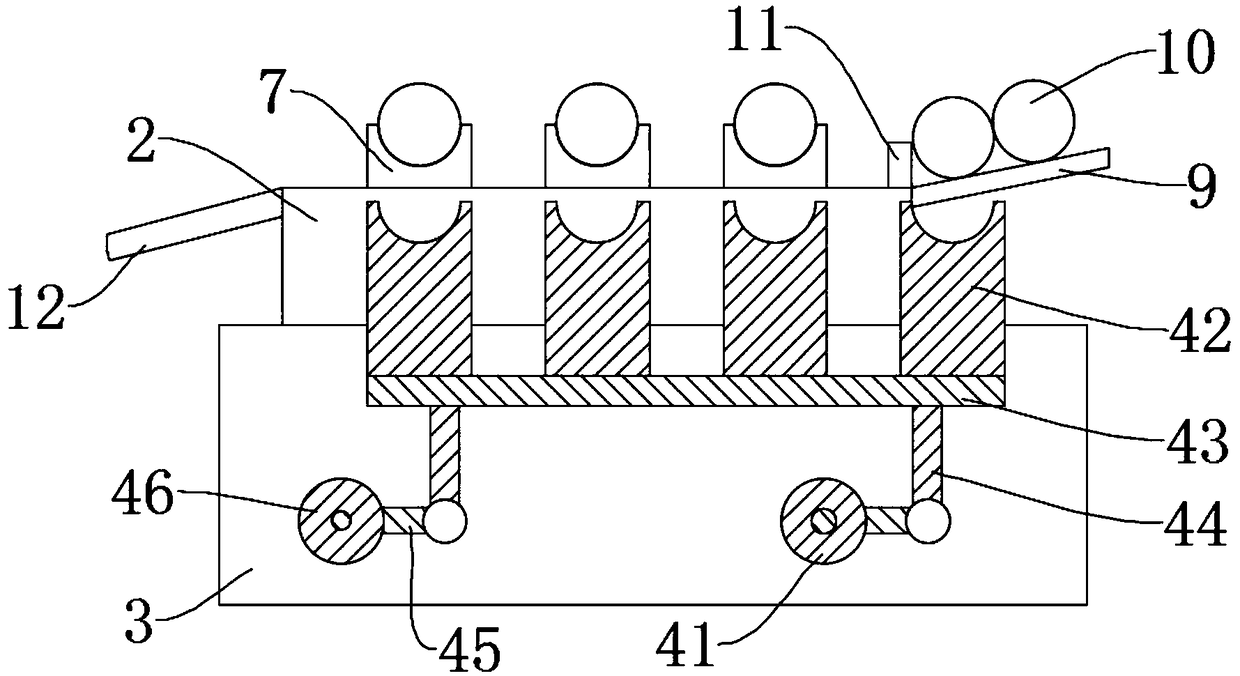
[0017] see Figure 1-4 , the present invention provides a technical solution: a high-performance alloy steel rod continuous forging device, including a workbench 1, a chute 2 is opened on the workbench 1, one end of the chute 2 is fixedly connected to a feed chute 9 on both sides, and the The steel bar 10 is slidably placed in the chute 9, the other end of the chute 2 is fixedly connected to the discharge chute 12, the workbench 1 on both sides o...


PUM


Abstract

The invention discloses a high-performance continuous forging and pressing device for alloy steel rods. The device includes a worktable, a sliding groove is formed in the worktable, a feeding groove is connected with one end of the sliding groove and contains the steel rods, the other end of the sliding groove is connected with a discharge groove, and a bearing platform is installed on the top ofthe sliding groove; fixing plates are installed on both sides of the bottom of the sliding groove, and a rotating shaft is rotatably sleeved with the fixing plates; a motor is installed on the fixingplate on one side of the sliding groove, an output shaft of the motor is connected with the rotating shaft, one end of the rotating shaft is provided with a conveying mechanism, the conveying mechanism is clamped into the sliding groove, a guide rail is installed on one side of the worktable, a clamping mechanism is installed between the guide rail and the other end of the rotating shaft, and a forging and pressing mechanism is installed on the other side of the worktable. The steel rods slide down along the feeding groove, the motor drives the rotating shaft to rotate, the conveying mechanismlifts the steel rods onto the bearing platform one by one, the rotating shaft drives the clamping mechanism to move at the same time, the clamping mechanism presses the steel rods on the bearing platform, and the forging and pressing mechanism conducts forging and pressing on the end face of each steel rod; after forging and pressing are finished, the clamping mechanism loosens the steel rods, and the conveying mechanism lifts the steel rods to the discharge groove.

Description

technical field [0001] The invention relates to the technical field of high-performance alloy steel bar processing equipment, in particular to a high-performance alloy steel bar continuous forging device. Background technique [0002] High-performance alloys refer to advanced high-temperature alloy materials and metals produced by the production technology of civilian products. They have the advantages of high strength, high toughness, high conductivity, corrosion resistance, high wear resistance, and high (low) temperature resistance. High-performance alloy steel rods made of alloys are often used for rotating shafts or connecting shafts in machinery. Before assembly, high-performance alloy steel rods need to be forged at both ends of the steel rods into a flat or square shape, and then matched with other parts. The existing Forging equipment needs manual loading and clamping before forging, and manual refueling after forging, which makes the forging process discontinuous a...

Claims


Application Information

Patent Timeline
Patent Type & Authority Applications(China)
IPC IPC(8): B21K1/06B21K27/00B21K27/02
CPCB21K1/06B21K27/00B21K27/02
Inventor 严冬祥
Owner 安徽震祥精工科技有限公司
Why Eureka
Try Eureka