A magnetic fluid mechanical arm

A technology of manipulators and magnetic fluids, applied in manipulators, program-controlled manipulators, manufacturing tools, etc., can solve the problems that the manipulator arm cannot be folded, hinders the movement and operation of personnel, and has a fixed telescopic range, so as to achieve rich bending forms and small space occupation , the effect of large bending range

Active Publication Date: 2020-09-01
CHINA UNIV OF MINING & TECH
View PDF6 Cites 0 Cited by
  • Summary
  • Abstract
  • Description
  • Claims
  • Application Information

AI Technical Summary

Problems solved by technology

There are still some deficiencies in the existing mechanical arms in use: the telescopic range of the mechanical arm is relatively fixed when in use, and has relatively large limitations; when the mechanical arm is connected with the machine, it is relatively fixed and has a single function; the mechanical arm is working It cannot be folded after the end, and it takes up a large space, which hinders the movement of personnel and later operations to a certain extent

Method used


Image

  • A magnetic fluid mechanical arm
  • A magnetic fluid mechanical arm
  • A magnetic fluid mechanical arm

Examples


Embodiment 1

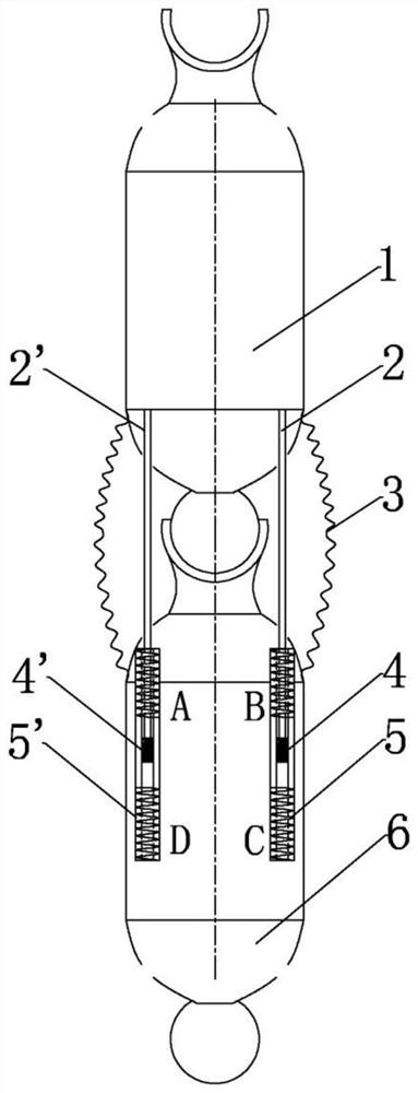
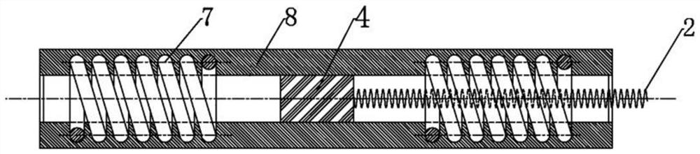
[0020] Such as figure 1 As shown, a magnetic fluid mechanical arm includes an upper limb rod 1 and a lower limb rod 6. The upper limb rod 1 and the lower limb rod 6 are connected by a spherical pair. One end of the foldable rubber sleeve 3 is connected to the upper limb rod 1 and the other end is connected to the The lower limb rod 6 and the folded rubber sleeve 3 protect the junction of the two rods, and can play a buffering role when the upper limb rod is bent. A pair of telescopic drive mechanisms 5 based on magnetic fluid are installed symmetrically in the longitudinal direction on the inner wall of the lower limb rod 6 , and the front end of the lower limb rod 6 has a hole. Such as figure 2 As shown, the telescopic drive mechanism 5 includes a plastic round tube 8, a magnetic fluid slider (4, 4') and a spring rod (2, 2'). The plastic round tube 8 has a coil 7 at both ends, and the coil 7 is connected to the current control device , the magnetic fluid slider (4, 4') can...

Embodiment 2

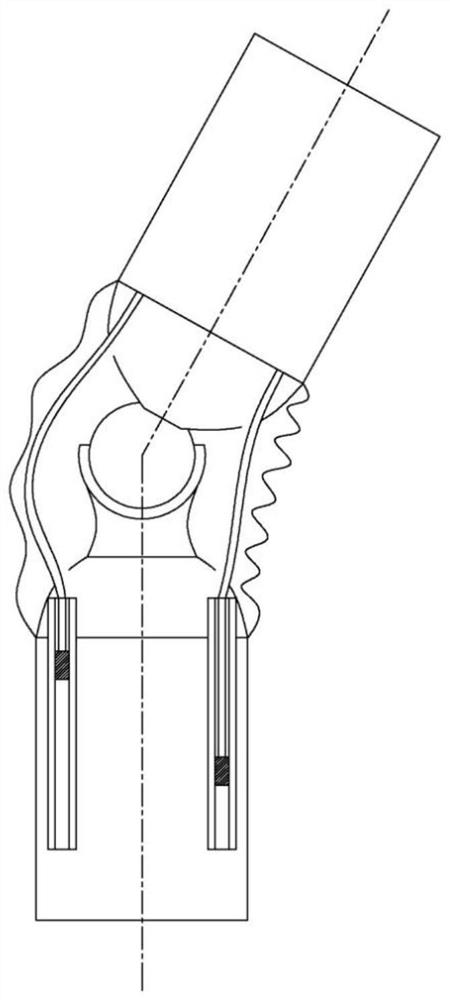
[0023] On the basis of Embodiment 1, multiple pairs of telescopic drive mechanisms 5 are symmetrically arranged on the lower limb rod 6 , and by cooperatively controlling the spring rods 2 of each telescopic drive mechanism 5 , the upper limb rod 1 can be coordinated and controlled to swing in any direction.

Embodiment 3

[0025] On the basis of Embodiments 1 and 2, the upper limb member 1 and the lower limb member 6 of the multi-section magnetic fluid manipulator are connected end to end to form a multi-section manipulator to achieve multi-stage bending.


PUM


Abstract

A magnetofluid manipulator comprises an upper arm member and a lower arm member connected via a spherical pair; the lower arm member has a plurality of telescoping drive mechanisms; each telescoping drive mechanism includes a guide rail, a magnetofluid slider and an elastic link, tow ends of the guide rail are provided with coils, one end of the elastic link is connected with the magnetofluid slider, and the other end of the elastic link is connected with the upper arm member. The magnetofluid manipulator provided herein is simple in structure and high in response speed; the multiple magnetofluid telescoping drive mechanisms on the lower arm member can telescope to different degrees such that the upper arm member can swing in any direction, the bending range is wide, and the applicable range is wide; when the multiple magnetofluid manipulators are combined, the magnetofluid manipulator units can be controlled and driven independently, the bending forms are rich, the bending range is wide, and the applicable range is wide; after working, the manipulator units are convenient to detach to use, so that small space is used.

Description

technical field [0001] The invention relates to a mechanical arm, in particular to a magnetic fluid mechanical arm. Background technique [0002] The robotic arm is a widely used automated mechanical device in the field of robotics. It can be seen in industrial manufacturing, medical treatment, entertainment services, military, semiconductor manufacturing, and space exploration. Although their shapes are different, But they can all accept instructions and precisely locate to a certain point in three-dimensional or two-dimensional space for operation. There are still some deficiencies in the existing mechanical arms in use: the telescopic range of the mechanical arm is relatively fixed when in use, and has relatively large limitations; when the mechanical arm is connected with the machine, it is relatively fixed and has a single function; the mechanical arm is working It cannot be folded after the end, and it takes up a large space, which hinders the movement of personnel an...

Claims


Application Information

Patent Timeline
Patent Type & Authority Patents(China)
IPC IPC(8): B25J9/10
CPCB25J9/10
Inventor 刘新华华德正陈凯凯李强杨虹
Owner CHINA UNIV OF MINING & TECH
Why Eureka
Try Eureka