Film piercing equipment

A technology of punching equipment and film, applied in mechanical equipment, metal processing, spring/shock absorber, etc., can solve the problems of unadjustable punching force, high energy consumption, complicated mechanism, etc., to reduce vibration, reduce noise, The effect of streamlining the transmission structure

Active Publication Date: 2019-01-25
SHANDONG SENBOSITE PLASTIC TECH CO LTD
View PDF6 Cites 0 Cited by
  • Summary
  • Abstract
  • Description
  • Claims
  • Application Information

AI Technical Summary

Problems solved by technology

However, there are problems that the punching force cannot be adjusted, the mechanism is too complicated, and the energy consumption is too high

Method used


Image

  • Film piercing equipment
  • Film piercing equipment
  • Film piercing equipment

Examples


Embodiment Construction

[0023] In order to make it easy to understand the technical means, creation features, achieved goals and effects of the present invention, the present invention will be further described below with reference to the specific embodiments.

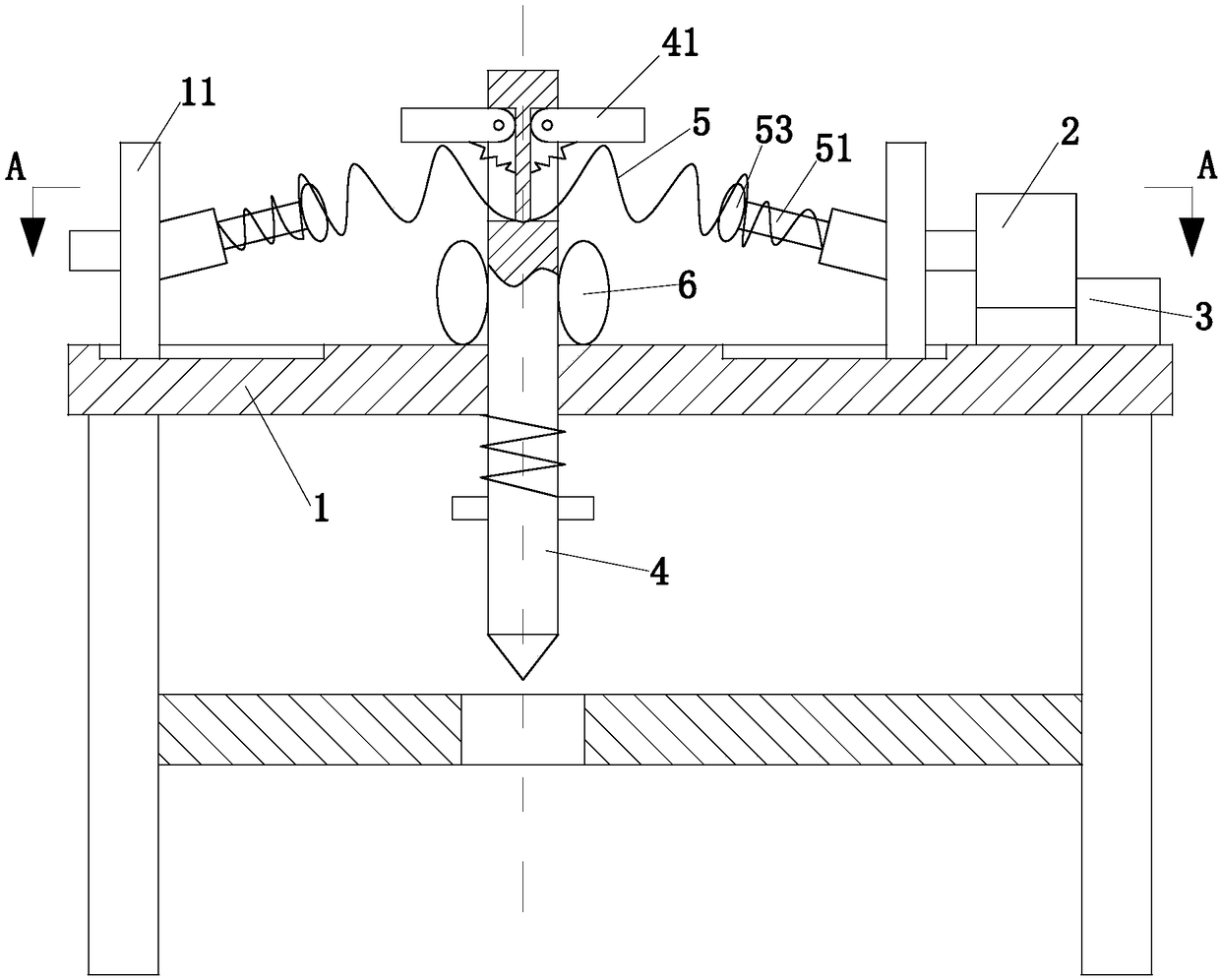
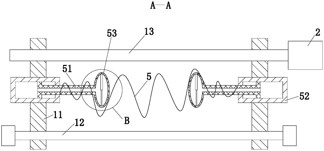
[0024] like Figure 1 to Figure 3 As shown, a film punching equipment according to the present invention includes a support 1, a motor 2, a controller 3, a slide plate 11, a punch 4, a clamping block 41, a spring 1 5, a guide rod 12 and a screw rod 13, The support 1 is provided with a chute, and there are two chute distributed symmetrically on both sides of the punch 4; the guide rod 12 is installed on the support 1, and the guide rod 12 is parallel to the plane of the support 1; the The sliding plate 11 is worn on the guide rod 12. There are two sliding plates 11 and are symmetrically distributed on both sides of the punch 4. The sliding plates 11 are respectively connected to the sliding grooves on both sides. Threaded connection, the lead...


PUM


Abstract

The invention belongs to the technical field of film piercing equipment, and particularly relates to film piercing equipment. The film piercing equipment comprises a support, a motor, a controller, sliding plates, a punch, a clamping block, a first spring, a guide rod, a lead screw and a controller, wherein a first air bag is arranged between the support and the clamping block; rubber bars are arranged at the two ends of the axis of the first spring; an inclined angle is formed between each rubber bar and the plane of the support; the rubber bars penetrate through the axis of the first springto erect up the first spring; a cylinder is arranged on each of the two sliding plates; each cylinder is fixed on the corresponding sliding plate; a telescopic rod is arranged in a second air bag; thetwo ends of the telescopic rod are fixed on the inner wall of the second air bag; two clamping grooves are formed in the outer wall of the second air bag; and the two clamping grooves are symmetrically formed in the upper end and the lower end of the second air bag. By a simple transmission structure, energy consumption for running of the equipment is reduced; and due to discontinuous working travels, the requirement for processing of scattered raw materials is met.

Description

technical field [0001] The invention belongs to the technical field of thin-film perforating equipment, in particular to a thin-film perforating equipment. Background technique [0002] After the crops are planted, in some arid areas with little rainfall and deserts, in order to increase the ground temperature and protect the soil moisture from being quickly evaporated, reduce the damage of weeds, and promote the better growth of crops, it is often necessary to cover the crops with a layer of film. After germination and unearthed, the roots of crops are easy to irrigate and fertilize, and it is necessary to manually tear the mulch film. However, the procedure of manually tearing the mulch film is cumbersome, labor-intensive, and waste of human and material resources. [0003] There are also some technical solutions for film punching in the prior art. For example, a Chinese patent with an application number of 2017204903891 discloses a film punching device, which includes a b...

Claims


Application Information

Patent Timeline
Patent Type & Authority Applications(China)
IPC IPC(8): B26F1/14B26D5/08B26D7/26B26D7/00F16F15/02F16F15/023F16F15/04F16F15/08
CPCB26D5/08B26D7/00B26D7/26B26F1/14F16F15/022F16F15/0232F16F15/046F16F15/08
Inventor 夏敏月闫羽
Owner SHANDONG SENBOSITE PLASTIC TECH CO LTD
Why Eureka
Try Eureka