Movable motor vehicle tire alignment placement mechanism

A centering mechanism and motor vehicle technology, applied in the direction of conveyors, conveyor objects, transportation and packaging, etc., can solve the problems of poor synchronization of left and right cylinders, inability to synchronize two cylinders, and high cost, so as to reduce collision damage, The structure of the device is simple and the operation is convenient

Inactive Publication Date: 2019-01-25
王少明
View PDF17 Cites 2 Cited by
  • Summary
  • Abstract
  • Description
  • Claims
  • Application Information

AI Technical Summary

Problems solved by technology

Although this structure is simple in structure, it also has very obvious disadvantages: the synchronization of the left and right cylinders is not good, because the gas is compressible, the friction force of the pistons of the two cylinders cannot be absolutely consistent,

Method used


Image

  • Movable motor vehicle tire alignment placement mechanism
  • Movable motor vehicle tire alignment placement mechanism
  • Movable motor vehicle tire alignment placement mechanism

Examples


Embodiment Construction

[0026] The following will clearly and completely describe the technical solutions in the embodiments of the present invention with reference to the accompanying drawings in the embodiments of the present invention. Obviously, the described embodiments are only some, not all, embodiments of the present invention. Based on the embodiments of the present invention, all other embodiments obtained by persons of ordinary skill in the art without making creative efforts belong to the protection scope of the present invention.

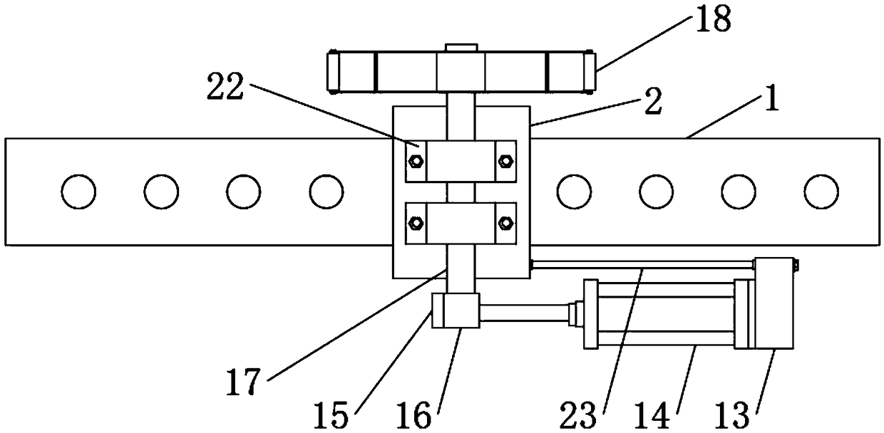
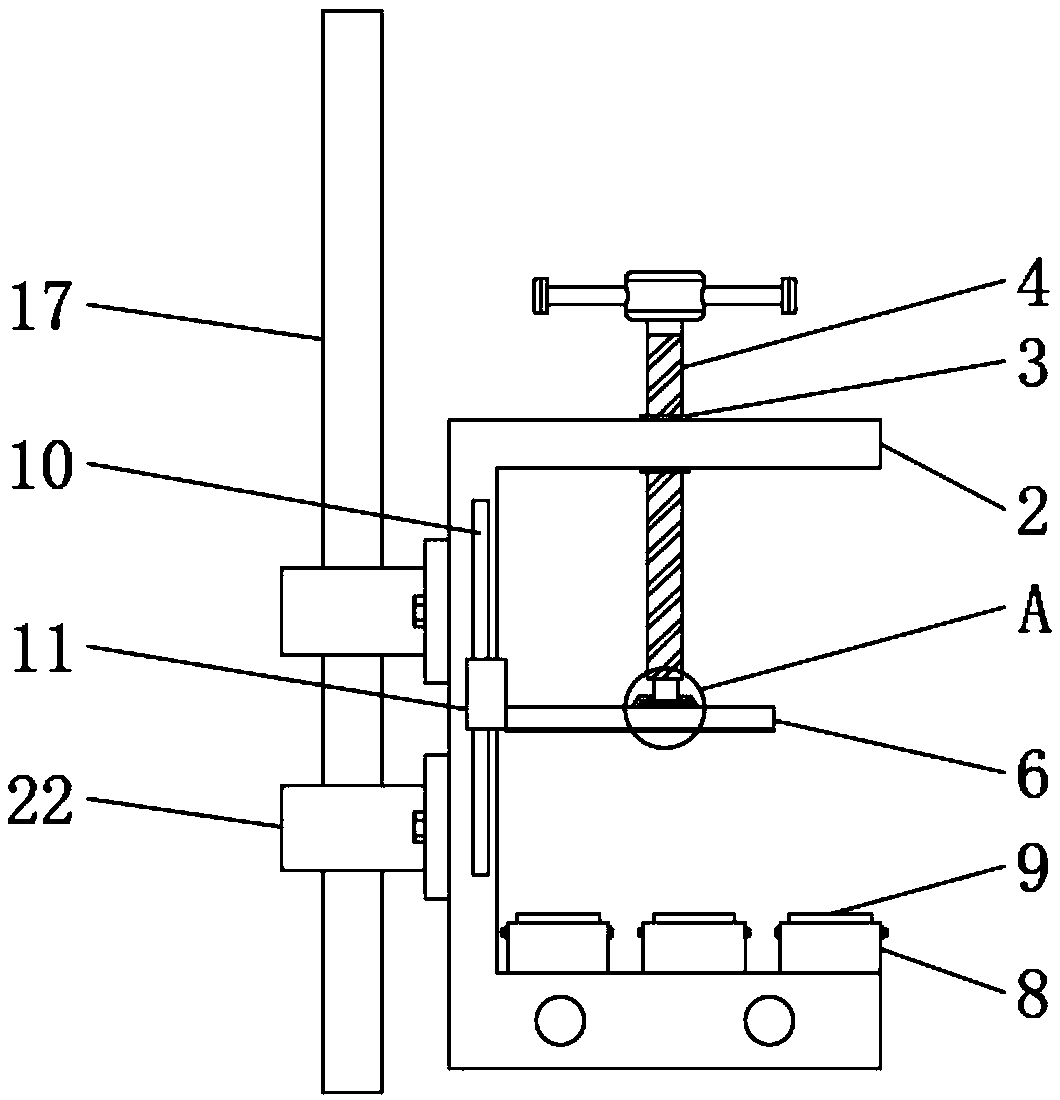
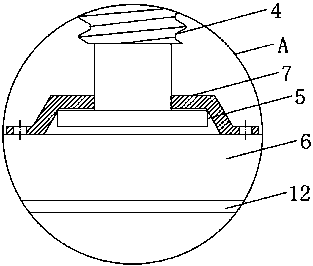
[0027] see Figure 1 to Figure 6 , the present invention provides a technical solution: a mobile vehicle tire centering mechanism, including a conveyor 1, a clamp mechanism and a centering mechanism, the clamp mechanism includes a clamp body 2 erected on the left and right sides of the conveyor 1, the clamp The top of the concrete 2 is fixedly connected to the inner nut sleeve 3, and the inner nut sleeve 3 is threadedly connected to the handle bolt 4, and the ...


PUM


Abstract

The invention discloses a movable motor vehicle tire alignment placement mechanism. The mechanism comprises a conveying machine, a clamp mechanism and an alignment mechanism. The clamp mechanism comprises clamp bodies erected at the left and right sides of the conveying machine. Inner nut bushes are fixedly connected to the tops of the clamp bodies, the inner nut bushes are in threaded connectionwith rotating handle bolts, clamping bodies are arranged at the bottom ends of the rotating handle bolts, the clamping bodies and the clamp bodies clamp a rack of the conveying machine, the alignmentmechanism comprises a supporting plate, the supporting plate is fixedly connected with an end cover of a cylinder, an output rod of the cylinder is fixedly connected with a movable arm, the movable arm is hinged to one ends of two connecting rods separately, the other ends of the connecting rods are fixedly connected with a rotating shaft, the rotating shaft is fixedly connected with an alignmentplate, by adopting the cylinder, thrust is transmitted to the movable arm in a mechanical mode, the connecting rods hinged to the movable arm can drive the rotating shaft to rotate, the action synchronization of the two alignment plates is good, the alignment plates can push tires to the center line, and the mechanism is simple in structure and convenient to operate.

Description

technical field [0001] The invention relates to the technical field of tire production equipment, in particular to a mobile vehicle tire centering mechanism. Background technique [0002] On the tire automatic production conveyor line, in order to meet the requirements of entering the next pallet, the tires need to be transported on the center line of the conveyor line, otherwise the tires entering the palletizer cannot be stacked neatly. [0003] At present, most of the tire centering and positioning devices are composed of two independent symmetrical mechanisms, and a cylinder is installed on the left and right sides. When the tire is centered and positioned, the cylinders on the left and right sides simultaneously push the pusher to position the tire through the linkage mechanism. . Although this structure is simple in structure, it also has very obvious disadvantages: the synchronization of the left and right cylinders is not good, because the gas is compressible, the f...

Claims


Application Information

Patent Timeline
IPC IPC(8): B65G47/28
CPCB65G47/28B65G2201/0273
Inventor 王少明
Owner 王少明
Why Eureka
Try Eureka