Method for load control of steam turbine in frequency-variable rotating speed reducing process of SHRT (sinter blower residual heat recovery turbine) set

A load control and steam turbine technology, applied in the direction of machines/engines, mechanical equipment, engine components, etc., can solve problems such as current reduction, DC bus voltage increase, fault tripping, etc., to achieve stable motor current, save electric energy, and meet requirements. high effect

Active Publication Date: 2019-01-25
XIAN SHAANGU POWER
View PDF8 Cites 5 Cited by
  • Summary
  • Abstract
  • Description
  • Claims
  • Application Information

AI Technical Summary

Problems solved by technology

[0005] At present, when the SHRT unit is in use, during the process of reducing the speed of the motor 4 through the frequency converter 7, the motor 4 will bear a large reverse torque due to the work of the steam turbine 1, causing the motor 4 to enter the power generation state (the speed of the generator stator is less than that of the rotor Speed) The current of the motor 4 keeps decreasing, and the inverter 7 reverses the input power, while the ordinary two-quadrant inverter does not have the function of reverse input, the DC bus voltage of the inverter 7 rises accordingly, and finally the fault trip of the inverter 7 causes Unit interlock shutdown

Method used


Image

  • Method for load control of steam turbine in frequency-variable rotating speed reducing process of SHRT (sinter blower residual heat recovery turbine) set
  • Method for load control of steam turbine in frequency-variable rotating speed reducing process of SHRT (sinter blower residual heat recovery turbine) set
  • Method for load control of steam turbine in frequency-variable rotating speed reducing process of SHRT (sinter blower residual heat recovery turbine) set

Examples


Embodiment Construction

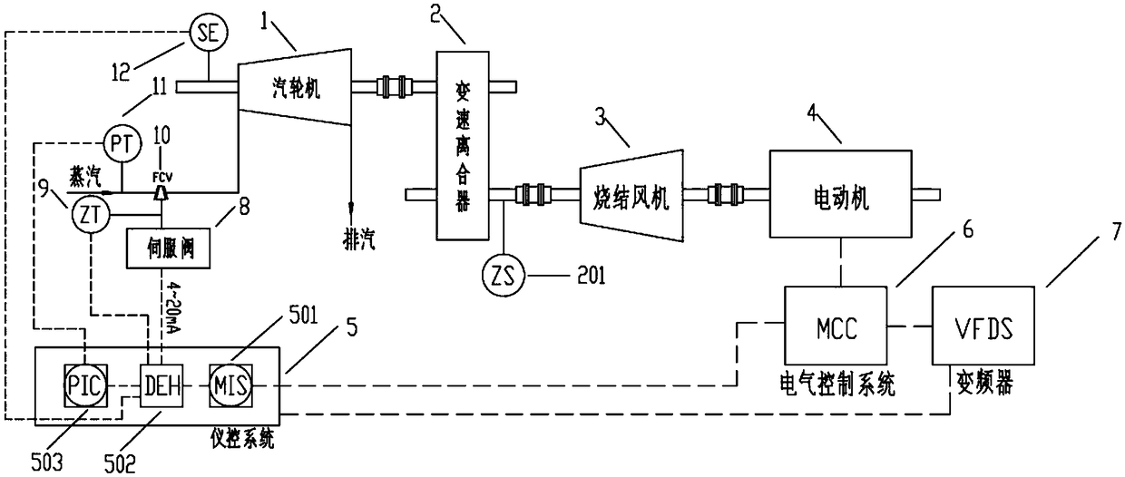
[0030] The present invention first analyzes the problems encountered by the unit in the process of frequency conversion adjustment and speed reduction through the research on the process system of the sintering waste heat recovery and the sintering fan combined drive unit, and the research on the working principle of the motor and its supporting frequency converter, and proposes the unit speed reduction control method.

[0031] The following is an analysis of the problems that may be encountered in the process of reducing the speed of the SHRT unit (hereinafter referred to as the unit) according to the attached drawings: When the unit is started and running normally, due to the change of working conditions (the demand for sintering exhaust air volume decreases), the unit It is necessary to reduce the speed to run, and the speed reduction process is dominated by the motor 4, and the steam turbine 1 cooperates with the speed regulation. Assuming that the steam turbine 1 does not ...


PUM


Abstract

The invention discloses a method for load control of a steam turbine in a frequency-variable rotating speed reducing process of an SHRT (sinter blower residual heat recovery turbine) set. The method includes: step 1, starting the steam turbine, and detecting regulating steam port openness when the steam turbine is in a maximum non-load speed; step 2, performing rotating speed reducing control of the set, to be more specific, 1) when rotating speed reducing operation of the set is needed, setting VFDS frequency or rotating speed by operating personnel; sending a 'preparing for rotating speed reduction' signal to an instrument control system by VFDS, judging whether the set meets speed regulating conditions or not by the instrument control system, and if yes, feeding a 'permission of rotating speed reduction' signal to VFDS7, and executing the step 2); 2) reducing the rotating speed of a motor to a target rotating speed S1 under the control of VFDS, and in a rotating speed reducing process, reducing output power of the steam turbine to guarantee that current of the motor is constantly set current II. The method is free of human intervention, and the problem of frequency converter failure shutdown caused by current fluctuation of the motor in the rotating speed reducing process is effectively solved; in addition, enormous economic benefits can be created for enterprises by the SHRT set.

Description

technical field [0001] The invention belongs to the technical field of waste heat power generation and is applied to energy recovery and utilization equipment in iron and steel metallurgical processes, in particular to a steam turbine load control method in the process of frequency conversion and speed reduction of SHRT units. Background technique [0002] The energy consumption of my country's iron and steel industry accounts for 16.3% of the country's total energy consumption, and its energy consumption is mainly from the two sections of sintering and ironmaking, of which the sintering section accounts for 10-20%, second only to 70% of the ironmaking section, so optimizing sintering Process and power equipment systems are particularly important to achieve energy saving and emission reduction. The sintering fan is a necessary active device for the sintering process, which is driven by a motor to supply air to the sintering system. The recovered waste heat of the sintering s...

Claims


Application Information

Patent Timeline
Patent Type & Authority Applications(China)
IPC IPC(8): F01D21/14F01D21/00F01D17/06
CPCF01D17/06F01D21/00F01D21/003F01D21/14
Inventor 马凯张亚军王东升王华强张保平柳黎光张娜
Owner XIAN SHAANGU POWER
Why Eureka
Try Eureka