
Anti-freezing device of faucet special for chemical engineering

A technology of antifreeze device and faucet, which is applied in the direction of valve device, valve for ventilation, function valve type, etc. It can solve problems such as inconvenient heat preservation, cracking of faucet body, complex structure, etc., to save resources, reduce trouble and waste Effect

Inactive Publication Date: 2019-01-25
湖南湘硕化工有限公司
View PDF0 Cites 0 Cited by
  • Summary
  • Abstract
  • Description
  • Claims
  • Application Information

AI Technical Summary

Problems solved by technology

If there are any problems in the production process, it may cause very serious accidents, such as corrosion or leakage of chemical reagents, etc., which poses a serious threat to the safety of the lives and property of the chemical plant workers, and will also cause major economic losses to the chemical plant. loss
[0003] At present, general-purpose faucets are used outdoors in cold seasons, especially in chemical plant areas. Due to structural reasons, it is very inconvenient to keep them warm. Even if they are kept warm, when the water valve is closed, the water outlet will reach the valve core due to vacuum. There is always chemical liquid. In the cold winter, some chemical liquids have a lower freezing point, which is easy to freeze and even crack the faucet body.
Once the chemical solution stored in the faucet freezes, it will affect the normal production of the chemical industry. It must be heated to melt the ice before it can be used normally, which is unhygienic and prone to danger; if the faucet is cracked or overflows, it must be replaced New faucets, on the one hand, waste valuable chemical resources, and on the other hand, cause economic losses to chemical producers
At present, the antifreeze faucets invented are relatively complicated in structure and not well promoted.

Method used


Image

  • Anti-freezing device of faucet special for chemical engineering
  • Anti-freezing device of faucet special for chemical engineering

Examples


Embodiment Construction

[0026] In order to enable those skilled in the art to better understand the technical solutions of the present invention, the present invention will be further described in detail below in conjunction with the accompanying drawings and specific embodiments.

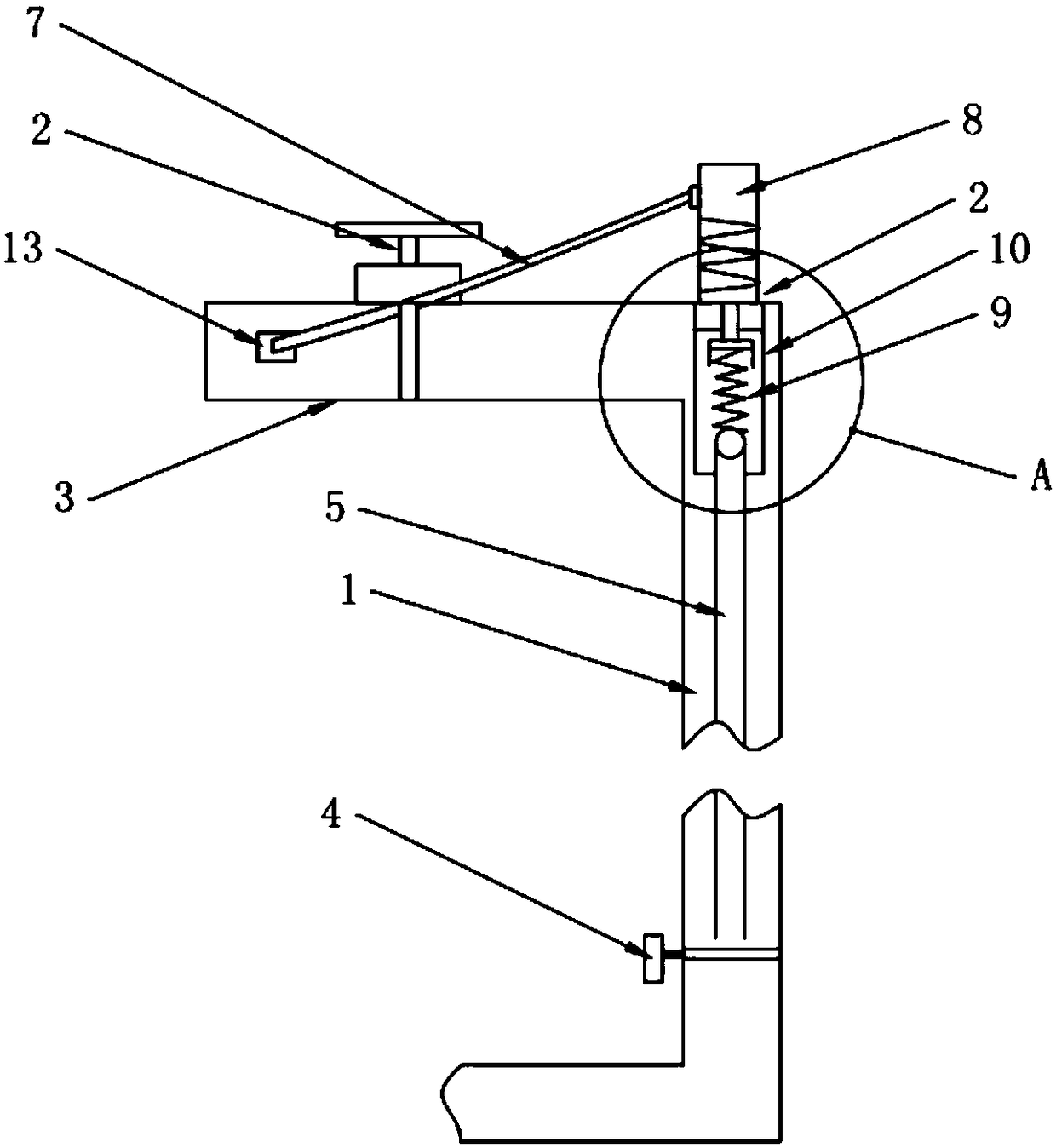
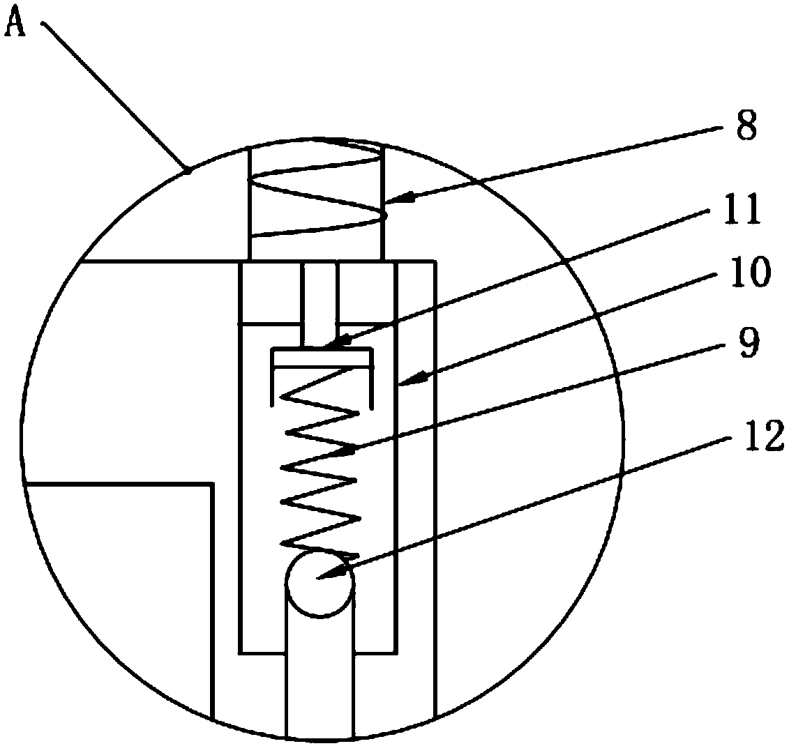
[0027] Such as Figure 1-2 As shown, an antifreeze device for a faucet includes a chemical solution inlet mechanism and a chemical solution discharge mechanism; the chemical solution inlet mechanism includes a chemical solution inlet pipe 1, a first valve body 2, and a chemical solution outlet pipe 3, and the chemical solution enters the pipe 1 and the chemical solution discharge pipe 3 are installed on the first valve body 2, and a liquid blocking member is installed on the chemical solution inlet pipe 1; the chemical solution discharge mechanism includes a suction pipe 5, a second valve body 6 and a liquid discharge pipe 7. The second valve body 6 is installed on the top of the liquid suction pipe 5, and the liquid suct...


PUM


Abstract

The invention discloses an anti-freezing device of a faucet special for chemical engineering. The device comprises a chemical solution feeding mechanism and a chemical solution discharging mechanism;the chemical solution feeding mechanism comprises a chemical solution feeding pipe, a first valve body and a chemical solution discharging pipe; the chemical solution discharging mechanism comprises aliquid suction pipe, a second valve body and a liquid discharging pipe, the second valve body is installed at the upper portion of the liquid suction pipe, the liquid suction pipe is disposed in thechemical solution feeding pipe, and the other end of the liquid suction pipe is connected with the second valve body; the second valve body comprises a pressing cover, a spring, a mounting cylinder, an exhaust valve and a liquid discharging valve, the liquid discharging pipe is communicated with the pressing cover, the pressing cover and the mounting cylinder are cooperatively installed, the exhaust valve is installed at the lower portion of the pressing cover, and the spring is cooperatively installed between the exhaust valve and the liquid discharging valve. The device is simple in structure and high in cost performance, and meanwhile the technical effects that anti-freezing can be conducted on water pipelines and residual liquid discharged out of the pipes can be fully utilized are achieved; unnecessary waste of chemical solution resources in normal use is avoided.

Description

technical field [0001] The invention relates to the field of special chemical pipeline valves, in particular to an antifreeze device for a special chemical faucet. Background technique [0002] The faucet is a switch used to control the flow of water, which has the effect of saving water. The replacement speed of faucets is very fast. In the process of chemical production, due to the very special working environment, more and more producers choose faucets in consideration of materials, functions, shapes and other aspects. If there are any problems in the production process, it may cause very serious accidents, such as corrosion or leakage of chemical reagents, etc., which poses a serious threat to the safety of the life and property of the chemical plant staff, and will also cause major economic losses to the chemical plant. loss. [0003] At present, general-purpose faucets are used outdoors in cold seasons, especially in chemical plant areas. Due to structural reasons, i...

Claims


Application Information

Patent Timeline
Patent Type & Authority Applications(China)
IPC IPC(8): F16K13/00F16K24/04
CPCF16K13/00F16K24/04
Inventor 滕冬成匡悦王爱国
Owner 湖南湘硕化工有限公司
Learn More