
Method for detecting obstacle of rubber tired crane at container port based on binocular vision

A technology of obstacle detection and binocular vision, which is applied to the interpretation of photos, etc., can solve problems such as maintenance difficulties, large labor costs, and inaccurate calculations

Inactive Publication Date: 2019-01-25
NANJING UNIV
View PDF12 Cites 16 Cited by
  • Summary
  • Abstract
  • Description
  • Claims
  • Application Information

AI Technical Summary

Problems solved by technology

[0005] 1. LiDAR is expensive
[0006] The cost of laser radar equipment is very high. A 32-line laser radar costs about 20,000 US dollars, while a 64-line laser radar costs as much as 80,000 US dollars.
[0007] 2. Lane lines cannot be detected without modification
[0008] The lidar-based obstacle detection system relies on reflective markings. If no special paint is applied to the lane line, the lidar-based detection system cannot detect lane lines and other signs, and can only manually delineate the detection area, or in the lane line Special coatings are applied on them, which brings a large labor cost to different ports
At the same time, it is difficult to maintain after installing reflective markers, which also increases the cost
[0009] 3. It is difficult to classify and identify obstacles
[0013] Monocular vision obstacle detection If the vision system wants to calculate the obstacle distance, it can only install the camera at a fixed height, direction, etc., and the deviation is large, or the distance of the obstacle can only be estimated, not accurately calculated , there is also a certain deviation
[0014] 2. There will be misrecognition of flat images
[0017] If the obstacle is very close to the camera, the system needs to alarm at this time, and the monocular visual obstacle detection system often cannot work normally in such a very dangerous situation, and there are serious safety hazards
[0018] 4. Only specific types of obstacles can be detected
[0020] Unable to detect obstacles other than training data

Method used


Image

  • Method for detecting obstacle of rubber tired crane at container port based on binocular vision
  • Method for detecting obstacle of rubber tired crane at container port based on binocular vision
  • Method for detecting obstacle of rubber tired crane at container port based on binocular vision

Examples


Embodiment

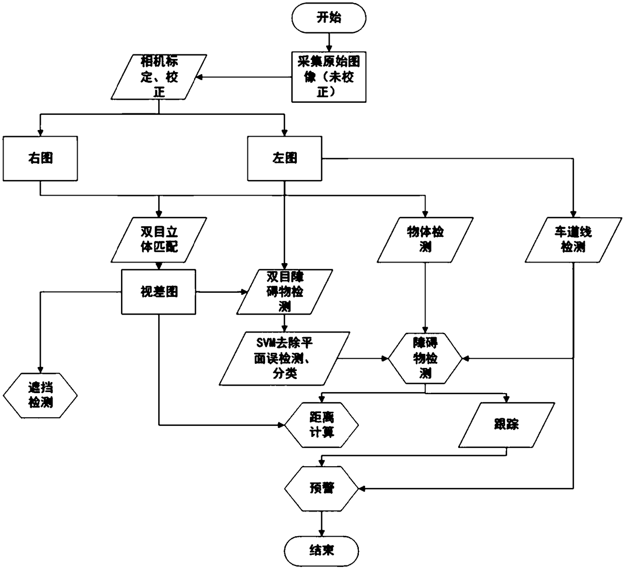
[0084] In order to make this system work better, first install the camera as required before. For the convenience of this embodiment, the same type of camera is used, and they are all fixed-focus cameras. The reason for fixed focus is to use the binocular model by parallax Calculate the distance to the obstacle. After the installation is completed, the left and right cameras are calibrated using the calibration board of Zhang’s calibration method to obtain the internal parameter I1 of the left camera and the internal parameter I2 of the right camera respectively. The resolutions of the left and right images collected in the embodiment are both 1280*960 pixels. In order to speed up the running speed of the program, except for the correction and disparity map, the resolution of 960*540 pixels is used, and all other functions are calculated at the resolution of 640*480 pixels.

[0085] Afterwards, this example performs stereo correction on the data collected by the binocular cam...


PUM


Abstract

The invention discloses a method for detecting an obstacle of a rubber tired crane at a container port based on binocular vision. The method comprises the following steps: step 1, collecting left andright images of an installed binocular camera; step 2, respectively correcting the left and right images, and removing distortion; step 3, by using the left image as a reference image, detecting a road line (region of interest (ROI)) on the image; step 4, enabling an obstacle detection module to detect the obstacle; step 5, judging the blocking of the camera; step 6, simply tracking the obstacle;if the obstacle moves towards the inner side of the road line (ROI), alarming.

Description

technical field [0001] The invention relates to a binocular vision-based obstacle detection method for a container terminal bridge. Background technique [0002] Rubber Tire Gantry (RTG, Rubber Tire Gantry) and Rail Mounted Gantry (RMG) (collectively referred to as yard bridges), as large-scale machinery in ports, play a vital role in port operations. Its efficiency, safety, and correctness of operation have an important impact on terminal operations. The yard bridge is mainly responsible for the container transfer between the container and the container stacked in the yard and the container horizontal transportation equipment (container truck or automatic guided transport vehicle AGV, running on the truck lane), which is characterized by complex operating environment and high risk factor , the driver has poor vision and is highly dependent on the driver. [0003] During yard and bridge operations, due to the high position of the driver's cab, the unsatisfactory lighting c...

Claims


Application Information

Patent Timeline
IPC IPC(8): G01C11/04
CPCG01C11/04
Inventor 李俊黄羽佳韩峰姜少魁申富饶赵健
Owner NANJING UNIV
Learn More