Underground water level remote automatic observation device

An automatic observation, groundwater level technology, applied in the direction of buoy liquid level indicator, etc., can solve the problems of national economic loss, unreliable work performance, untimely water level monitoring, etc., and achieve stable and reliable work performance.

Pending Publication Date: 2019-01-25
CHINA POWER CONSRTUCTION GRP GUIYANG SURVEY & DESIGN INST CO LTD
View PDF0 Cites 2 Cited by
  • Summary
  • Abstract
  • Description
  • Claims
  • Application Information

AI Technical Summary

Problems solved by technology

[0002] The so-called groundwater level observation device is mainly used to observe or monitor the change of groundwater level. Groundwater is a precious natural resource and one of the main water sources for human survival. In recent years, due to excessive exploitation of engineering activities and unreasonable use of human beings , often causes the groundwater level to drop, and when the precipitation funnel is serious, it may even cause geological problems such as uneven subsidence of the stratum and goaf collapse, resulting in major national economic losses. The dynamic change of watershed level is the core content of finding out the mutual replenishment or discharge of groundwater in the subsidence area. For monitoring and researching the relationship between groundwater and surface water, and for reservoir seepage control, it is necessary to understand the change of watershed water level. A kind of Remote groundwater automatic observation device can meet this requirement
However, the existing remote automatic observation device for groundwater level mainly has the disadvantages of complex structure, unreliable working performance, untimely water level monitoring, inconvenient water level observation and inability to remind and warn operators when the water level exceeds the warning line. Some groundwater level remote automatic observation devices still cannot meet the needs of use

Method used


Image

  • Underground water level remote automatic observation device
  • Underground water level remote automatic observation device
  • Underground water level remote automatic observation device

Examples


Embodiment Construction

[0016] The present invention will be further described in detail below in conjunction with the accompanying drawings and embodiments.

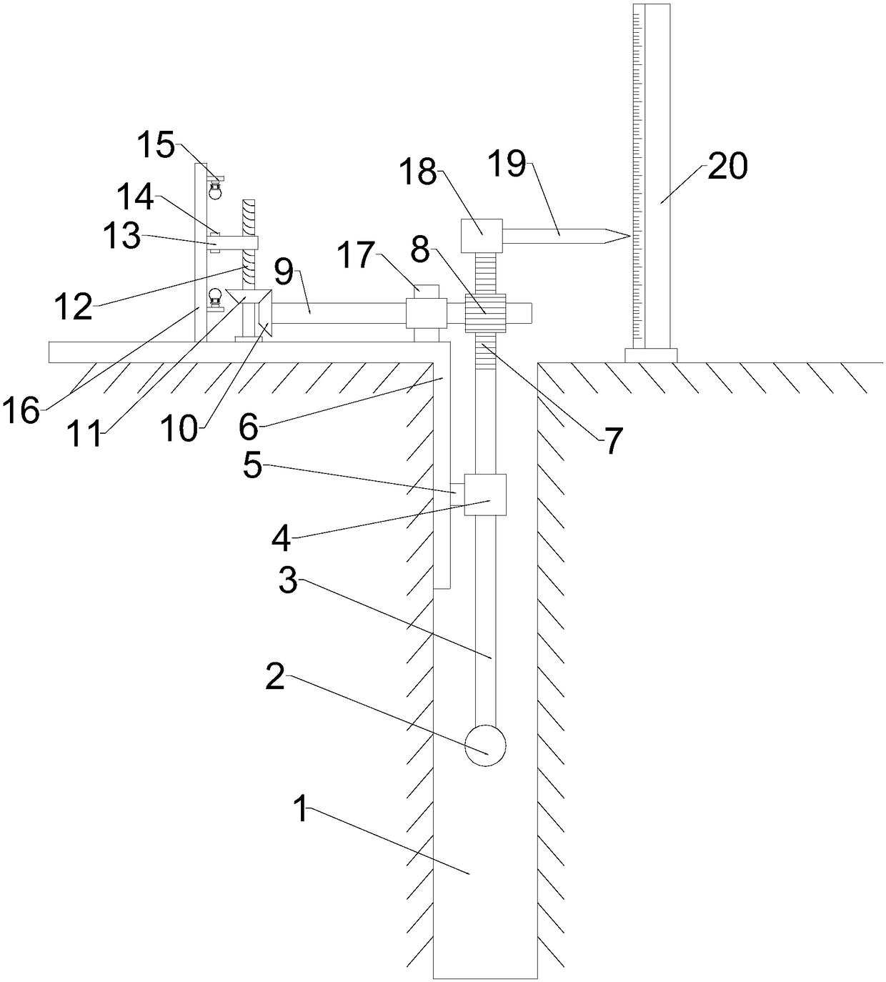
[0017] A remote automatic observation device for groundwater level of the present invention, such as figure 1 and 2 As shown, the device includes a borehole 1 that goes deep into the groundwater. The depth of the borehole 1 can be determined according to the needs of use. A fixed seat 6 and a measuring ruler 20 are fixed on the ground at the upper end of the borehole 1. The fixed seat 6 is L-shaped. structure, one side of the L-shaped structure of the fixed seat 6 is a horizontal bar, and the horizontal bar is fixed on the upper end surface of the borehole 1 through a ground pin, and the other side of the L-shaped structure of the fixed seat 6 is a vertical bar, and the vertical bar Vertically extending into the borehole 1, a floating ball 2 is arranged in the borehole 1, the floating ball 2 is fixedly connected with the connecting rod 3, the...


PUM


Abstract

The invention discloses an underground water level remote automatic observation device. A fixed seat and a measuring scale are arranged on the upper ground of a drilled hole, a floating ball is arranged in the drilled hole and fixedly connected with a connecting rod, the connecting rod is slidably connected in a sleeve in a sleeving manner, the sleeve is fixedly connected with a slider, the slideris slidably connected with a vertical rod of the fixed seat, a marking rod and a connector are fixed at the upper end of a rack of the connecting rod, the pointer end of the marking rod approaches toa scale position of the measuring scale, the rack is engaged with a gear, the gear is fixed with a rotating rod, the rotating rod is connected with the fixed seat through a bearing, a driving bevel gear is arranged on the rotating rod and engaged with a driven bevel gear, the driven bevel gear is fixedly mounted on a threaded rod, the threaded rod is rotatably connected with the fixed seat through the bearing, a threaded hole slider is connected on the threaded rod in a threaded manner, and alarm devices are arranged at the upper end and the lower end of a supporting plate fixed onto the fixed seat and can contact with the threaded hole slider. The device has the advantages of simple structure, reliability in working and the like.

Description

technical field [0001] The invention relates to a remote automatic observation device for underground water level, which belongs to the technical field of underground water level observation device for engineering geology. Background technique [0002] The so-called groundwater level observation device is mainly used to observe or monitor the change of groundwater level. Groundwater is a precious natural resource and one of the main water sources for human survival. In recent years, due to excessive exploitation of engineering activities and unreasonable use of human beings , often causes the groundwater level to drop, and when the precipitation funnel is serious, it may even cause geological problems such as uneven subsidence of the stratum and goaf collapse, resulting in major national economic losses. The dynamic change of watershed level is the core content of finding out the mutual replenishment or discharge of groundwater in the subsidence area. For monitoring and rese...

Claims


Application Information

Patent Timeline
Patent Type & Authority Applications(China)
IPC IPC(8): G01F23/60
CPCG01F23/60
Inventor 陈兵曾荣福
Owner CHINA POWER CONSRTUCTION GRP GUIYANG SURVEY & DESIGN INST CO LTD
Why Eureka
Try Eureka