Anti-atomization device for fuel nozzle test bench

A technology of fuel nozzles and test benches, which is applied in the direction of measuring devices, engine tests, and mechanical parts tests, etc. It can solve the problems of limited function, interference test results, and improvement of test result accuracy, so as to prevent rebound, increase contact area, The effect of reducing interference

Pending Publication Date: 2019-01-25
PLA NO 5719 FACTORY
View PDF0 Cites 4 Cited by
  • Summary
  • Abstract
  • Description
  • Claims
  • Application Information

AI Technical Summary

Problems solved by technology

However, the technical difficulty is that the fuel sprayed from the nozzle is highly atomized under high pressure. In addition to the measurable conical spray, the inner cavity of the test bench will also be filled with finer particles of suspended high-concentration oil mist, which will interfere Atomization quality and atomization angle test accuracy; the existing solution is to test under high-intensity light irradiation to reduce errors, but the effect of this method is limited, and the fine suspended high-concentration oil mist still fills the inner cavity of the test bench , part of the suspended oil droplets hit the inner wall of the test bench and rebounded, and returned to the conical spray test area under the action of the internal high-speed airflow, which interfered with the test results, resulting in a bottleneck in the improvement of the accuracy of the test results

Method used


Image

  • Anti-atomization device for fuel nozzle test bench
  • Anti-atomization device for fuel nozzle test bench
  • Anti-atomization device for fuel nozzle test bench

Examples


Embodiment Construction

[0031] In order to have a clearer understanding of the technical features, purposes and effects of the present invention, the specific implementation of the present invention will now be described with reference to the accompanying drawings, but the protection scope of the present invention is not limited to the following description.

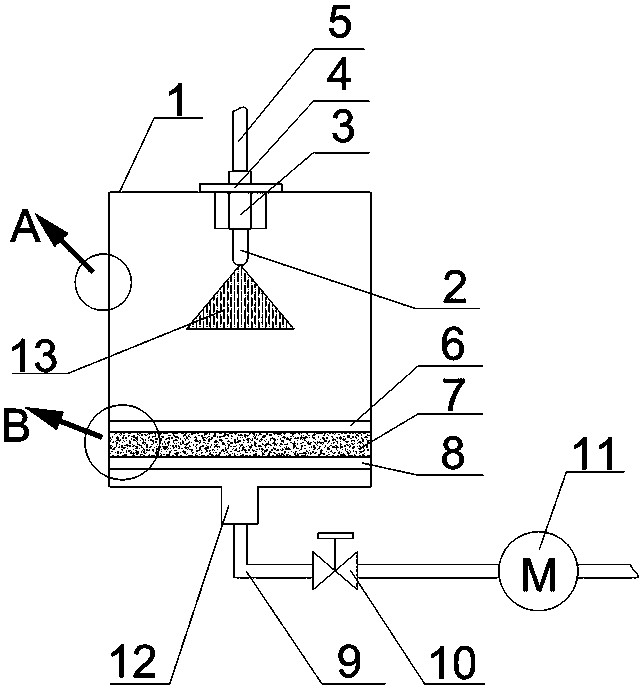
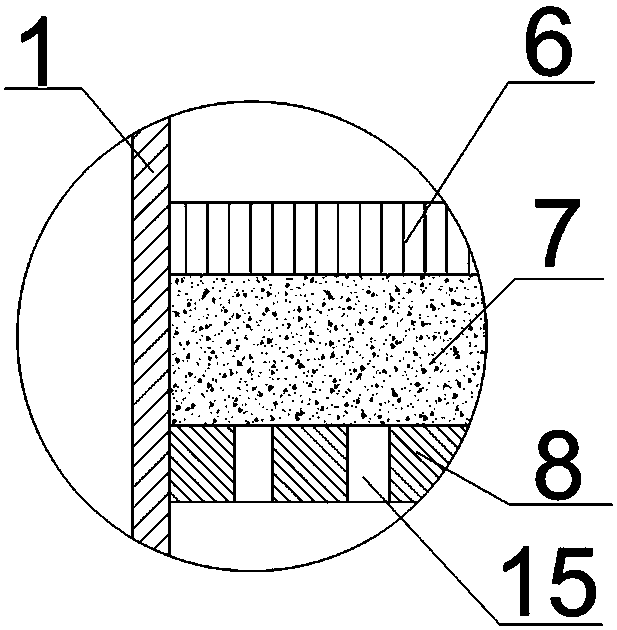
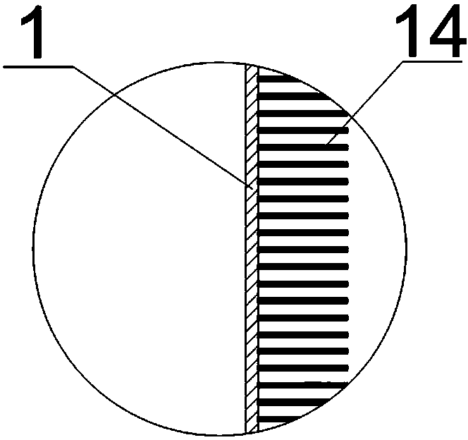
[0032] Such as figure 1 with figure 2 As shown, the present invention provides an anti-fog device for a fuel nozzle test bench, which includes a test bench case 1, the fuel nozzle 2 is installed above the interior of the test bench case 1, and the interior of the test bench case 1 also includes a filamentous adsorption layer 7 , flow stabilizing plate 8 and air suction port 12, wherein: the filamentous adsorption layer 7 is arranged below the fuel nozzle 2, and the steady flow plate 8 is arranged below the filamentary adsorption layer 7 for evenly passing the air flow; the suction port 12 is arranged at Below the stabilizing plate 8, it is us...


PUM


Abstract

The invention discloses an anti-atomization device for a fuel nozzle test bench. The device comprises a test bench box body; a fuel oil nozzle is installed at the upper part of the interior of the test bench box body; a filamentous adsorption layer, a flow stabilization plate and an air suction port are arranged in the test bench box body; the filamentous adsorption layer is disposed below the fuel oil nozzle; the flow stabilization plate is disposed below the filamentous adsorption layer; and the air suction port is disposed below the flow stabilization plate. The anti-atomization device of the invention generates uniform negative pressure in the vicinity of the filamentous adsorption layer, and therefore, the interference of air suction on the atomization angle of the nozzle can be decreased; the filamentous adsorption layer can effectively prevent the rebound of atomized fuel oil particles and better adsorb suspended oil droplets; the inner surface of the test bench box body is provided with hairy objects, and oil mist is directly adsorbed on the hairy objects; a steel wire mesh can be adjusted so as to move up and down, so that the thickness and density of the filamentous adsorption layer can be adjusted; a flow rate regulating valve is used for adjusting the flow rate of the suction port, so that influence on the test area of the inner cavity of a test bench caused by a too large air suction flow rate can be prevented.

Description

technical field [0001] The invention relates to the field of accessory devices of a fuel nozzle test device, in particular to an anti-fog device for a fuel nozzle test bench. Background technique [0002] Fuel nozzles are key components of aero-engines and have a significant impact on the performance of aero-engine combustors. The minimum ignition energy of the oil mist is proportional to the average Sauter diameter of the oil mist. The larger the SMD, the more difficult it is to ignite; the coarse mist in the flame tube can pass through the gas to reach the inner wall of the flame tube, causing the wall to overheat and coke; Uneven thickness will cause uneven temperature field at the outlet of the combustion chamber; if the spray cone angle is too large, the oil droplets will be so large that the inner wall of the flame tube will cause head ablation; if the spray cone angle is too small, more oil droplets will be concentrated in the center of the flame tube for combustion ...

Claims


Application Information

Patent Timeline
Patent Type & Authority Applications(China)
IPC IPC(8): G01M13/00G01M15/02
CPCG01M13/00G01M15/02
Inventor 谢长城付俊波
Owner PLA NO 5719 FACTORY
Why Eureka
Try Eureka