

A vibration signal denoising method and system based on independence
A vibration signal and independent technology, which is applied to the recognition of patterns in signals, instruments, characters and patterns, etc., can solve the problems of amplitude uncertainty, unsatisfactory separation results, and influence on separation effects, etc., to achieve feature extraction, Solve the problem of algorithm failure and accurately determine the effect
- Summary
- Abstract
- Description
- Claims
- Application Information
AI Technical Summary
Problems solved by technology
Method used
Image

Examples
specific Embodiment 1
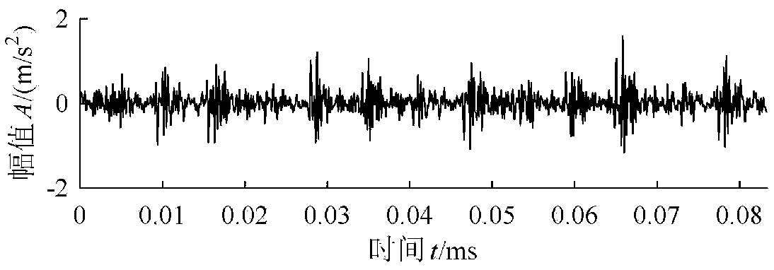
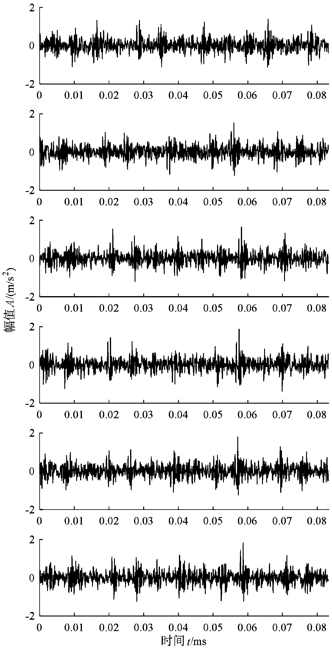
[0099] The fault data s of the inner ring of the rolling bearing collected by the acceleration sensor, such as figure 2 shown. Add 15dB noise to s to generate six noisy signals as simulation signals, such as image 3 As shown, these six signals are denoised.
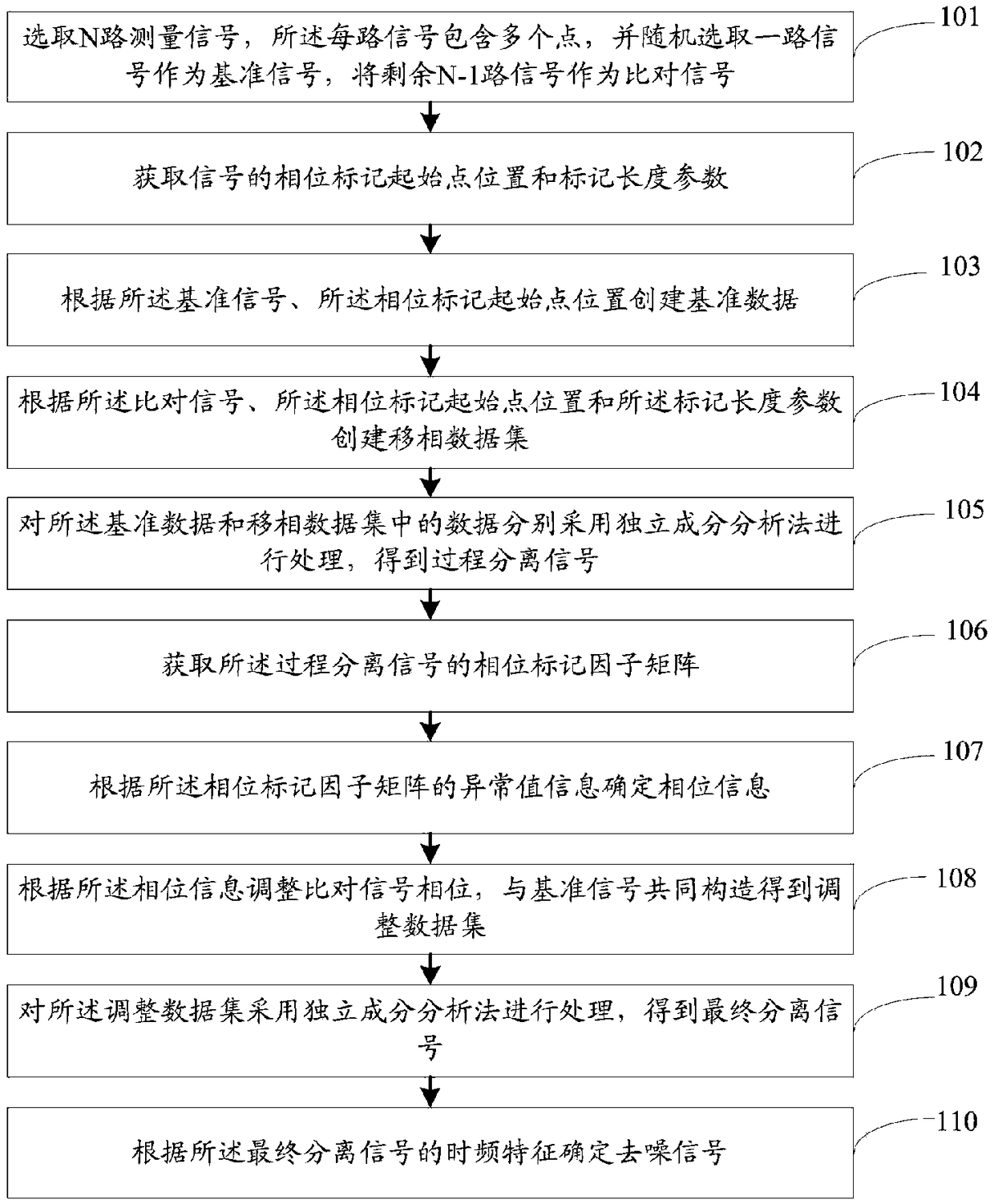
[0100] Step 1: Take one of the six signals as the reference signal X 0 , the other five signals are comparison signals X1={X 1 ,X 2 ,...,X 5}, take 5000 points for each signal;
[0101] Step 2: Set the parameters, select the position of the 1000th point as the starting point of the phase mark τ 0 , the mark length parameter m=200, respectively at the starting point τ of the phase mark 0 Take 200 points on the left side and 200 points on the right side.
[0102] Step 3: According to the reference signal X 0 Create the reference data S, a total of 1000 points of data in S, and create a phase-shifting data set X2 according to the signals of different phase starting points:
[0103]
[0104] There are 1000 poin...
specific Embodiment 2
[0113] The acceleration sensor is used to collect the fault signal s of the inner ring of the rolling bearing, but there are other signals that interfere with the measured value. This interference signal is s’. The two signals are as follows: Figure 7 shown. Due to the different sensor positions, the two signals are mixed in the following mixing matrix:
[0114]
[0115] According to the formula X=H×(s, s’)’, the two-way mixed signal X={X 1 ,X 2},Such as Figure 8 shown. For a more accurate analog sampling signal, arrange a certain phase difference for the mixed signal X to obtain the simulated signal S={S 1 ,S 2}.
[0116] Step 1: S is the sensor sampling data obtained by simulation, where S is selected 1 As the benchmark data, select S 2 For data comparison, 5000 points are taken for each signal.
PUM
 Abstract
Description
Claims
Application Information