
Monitoring system and monitoring method for safe power consumption in distribution station area

A technology for safe electricity consumption and distribution station area, applied in the field of electric power, can solve problems such as frequent tripping of leakage switches, over-level tripping of leakage protection switches, failure of leakage protection switches, frequent occurrence of leakage hazards, etc., to achieve the effect of ensuring electricity safety and improving work efficiency

Pending Publication Date: 2019-01-25
江西菲可思测控技术有限公司
View PDF0 Cites 5 Cited by
  • Summary
  • Abstract
  • Description
  • Claims
  • Application Information

AI Technical Summary

Problems solved by technology

[0003] There are many types of electrical equipment in the distribution station area, complex wiring, and frequent hidden dangers of leakage. Due to the lack of necessary monitoring methods, it is difficult to accurately locate the leakage area and quickly eliminate faults, resulting in frequent tripping of the leakage switch and prominent tripping by leapfrogging, which seriously affects the power consumption of users.
In order to eliminate the interference caused by frequent tripping of the leakage switch, it is very common for the leakage protection switch to be shorted privately or even not put into use, which makes the three-level leakage protection in the station area useless and becomes a huge hidden danger for the safe use of electricity in the station area

Method used


Image

  • Monitoring system and monitoring method for safe power consumption in distribution station area

Examples


Embodiment Construction

[0032] In order to make the purpose, features and advantages of the present invention more obvious and understandable, the specific implementation manners of the present invention will be described in detail below in conjunction with the accompanying drawings. Several embodiments of the invention are shown in the drawings. However, the present invention can be embodied in many different forms and is not limited to the embodiments described herein. Rather, these embodiments are provided so that the disclosure of the present invention will be thorough and complete.

[0033] It should be noted that when an element is referred to as being “fixed on” another element, it may be directly on the other element or there may be an intervening element. When an element is referred to as being "connected to" another element, it can be directly connected to the other element or intervening elements may also be present. As used herein, the terms "vertical," "horizontal," "left," "right," "u...


PUM


Abstract

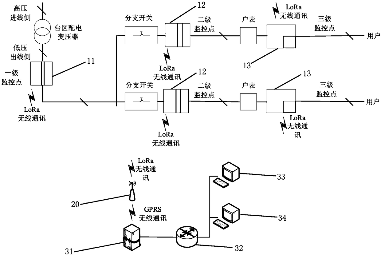
The invention discloses a monitoring system and a monitoring method for safe use of electricity in a distribution station area, the system comprises a field monitoring terminal, Data concentrators andmonitoring master stations, A field monitoring terminal is composed of a first-level leakage monitoring terminal and a second-level leakage monitoring terminal, A second-level leakage monitoring terminal and a third-level leakage monitoring terminal are formed, the first-stage leakage monitoring terminal is a B-type leakage monitoring terminal installed at the low-voltage outlet terminal of the distribution transformer in the station area, the second-level leakage monitoring terminal is a B-type leakage monitoring terminal installed at the outlet of the branch switch, the third-level leakagemonitoring terminal is a B-type leakage monitoring terminal installed at the lower port of the household meter, The first level leakage monitoring terminal, the second level leakage monitoring terminal and the third level leakage monitoring terminal are used for collecting leakage current data and uploading the data to the data concentrator by a LoRa communication mode, and the data concentrator uploads the collected data to the monitoring master station by GPRS communication mode. The invention can accurately locate the leakage section and ensure the safety of power consumption in the stationarea.

Description

technical field [0001] The invention relates to the field of electric power technology, in particular to a monitoring system and monitoring method for safe electricity use in a distribution station area. Background technique [0002] In order to ensure the safety of electricity consumption, a leakage protection switch needs to be installed in the distribution station area, which is generally divided into three levels: the first-level leakage protection, that is, the total leakage protection of the distribution transformer, which is set on the low-voltage main power supply side of the distribution transformer, and is the general protection switch of the station area. Protection; secondary leakage protection, that is, branch line leakage protection, is set on the power supply side of the line branch, mainly to prevent accidents such as leakage and grounding on the line branch and the power supply side entering the meter box; three-level leakage protection, that is, terminal hou...

Claims


Application Information

Patent Timeline
Patent Type & Authority Applications(China)
IPC IPC(8): H02J13/00
CPCH02J13/0075Y04S40/126Y02B90/20
Inventor 李艳
Owner 江西菲可思测控技术有限公司
Learn More