
Method for implementing carrier frequency offset correction base on large-point FFT

A technology of carrier frequency offset and implementation method, which is applied in the field of signal processing, can solve the problems of consuming large hardware resources, etc., and achieve the effect of improving frequency resolution, improving operation efficiency, and increasing operation complexity

Active Publication Date: 2019-01-25
UNIV OF ELECTRONICS SCI & TECH OF CHINA
View PDF6 Cites 9 Cited by
  • Summary
  • Abstract
  • Description
  • Claims
  • Application Information

AI Technical Summary

Problems solved by technology

[0006] However, as the number of points increases, direct calculation will consume a large amount of hardware resources, which cannot be satisfied by the current hardware, so it is necessary to study equivalent alternative algorithms

Method used


Image

  • Method for implementing carrier frequency offset correction base on large-point FFT
  • Method for implementing carrier frequency offset correction base on large-point FFT
  • Method for implementing carrier frequency offset correction base on large-point FFT

Examples


Embodiment

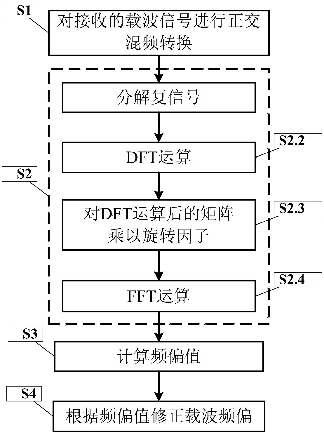
[0030] figure 1 It is a flow chart of an implementation method for correcting carrier frequency offset based on large-point FFT.

[0031] In this example, if figure 1 Shown, the present invention a kind of realization method based on the FFT correction carrier frequency offset of large number of points, comprises the following steps:

[0032] S1. Perform quadrature mixing conversion on the received carrier signal

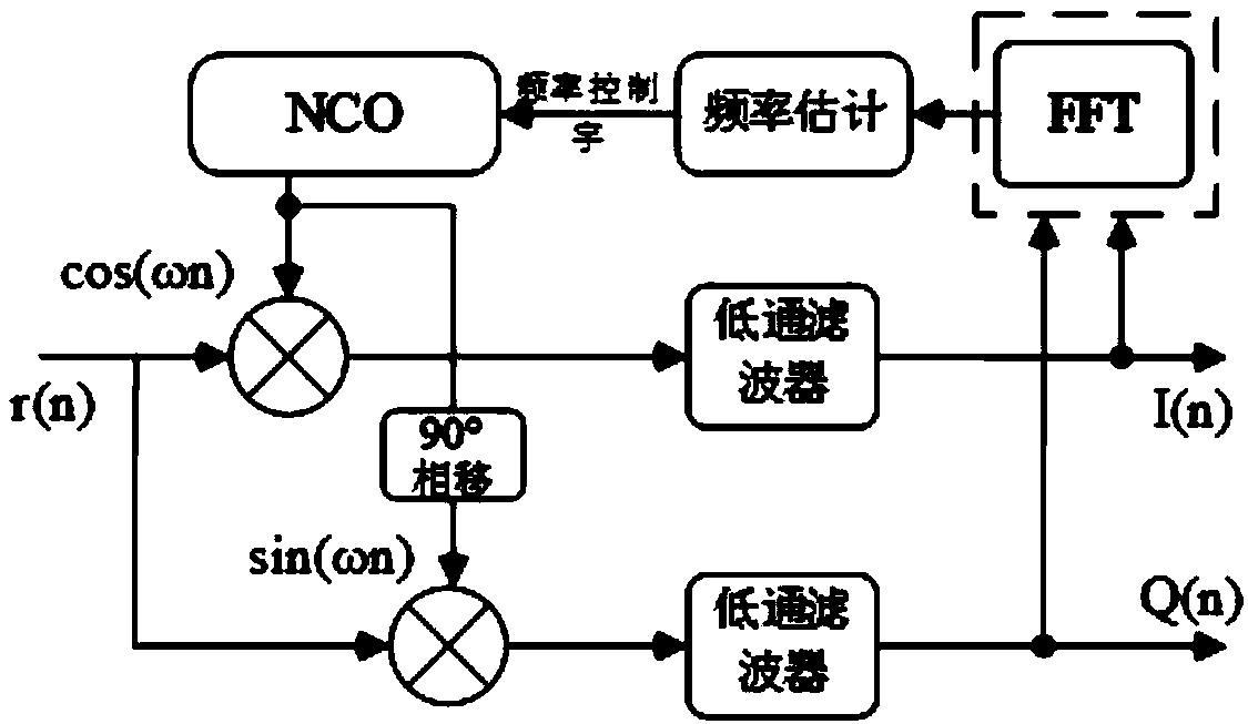
[0033] Taking the 16QAM signal as an example, let the received signal be f 0 is the frequency of r(n); without considering the influence of timing synchronization, inter-symbol interference and noise, r(n) is mixed with the quadrature local oscillator signal generated by the local voltage-controlled oscillator NCO, and then processed by low After the high-frequency components are filtered out by the pass filter, it is converted into two channels of I and Q, respectively:

[0034] I(n)=Acos[2πΔfnT s +θ 0 ]

[0035] Q(n)=Asin[2πΔfnT s +θ 0 ]

[0036] Among...

example

[0066] In this embodiment, taking the 256QAM signal as an example, the carrier frequency deviation of the demodulated baseband signal received is Δf=40MHz, and the sampling rate is F s = 100MHz, the symbol rate is R s =5MSps, the number of FFT points is N=1M.

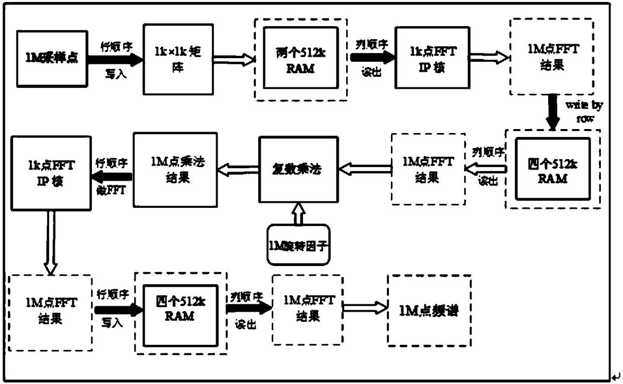
[0067] Synthesize the I and Q signals after quadrature mixing into a complex signal and do two matrix FFT analysis to obtain the spectrum characteristics.

[0068] Among them, the two matrix FFT steps are as follows:

[0069] 1) Arrange the sampled 1M points in row order to obtain a 1k×1k sampling point matrix, and then read them out in column order. This is mainly to operate on the RAM IP core, using two 512kRAMs to store 1M points. Write in row order and read out in column order.

[0070] 2) For the 1k×1k sampling point matrix, perform FFT of 1k points on each column of data read out to obtain a result matrix of 1M points, and store them in column order, and then read the result matrix of 1M points in row order o...


PUM


Abstract

A method for implementing carrier frequency offset correction base on large-point FFT. Firstly, the receive signal is orthogonally mixed, convert to I, Q two-way signal, and then combining the outputsignals of I and Q into complex signals, the spectrum characteristics of complex signals are estimated by using the twice FFT matrix method, and then finding the position corresponding to the maximumpeak point on the spectrum characteristic and calculating the frequency offset value, Finally, the frequency offset value is converted into the frequency control word of the voltage controlled oscillator, so as to generate the same frequency as the frequency offset value. After passing through the feedback loop, I and Q signals are compensated by orthogonal mixing, and the high-frequency components are eliminated through the low-pass filter to output the correct baseband signal after the frequency offset is eliminated.

Description

technical field [0001] The invention belongs to the technical field of signal processing, and more specifically relates to a method for implementing carrier frequency offset correction based on large-point FFT. Background technique [0002] In wireless communication, if any of the communicating parties is in a mobile state, the received signal will generate a Doppler frequency shift, and the Doppler frequency shift is an important reason for the carrier frequency difference. In addition, due to the limitation of the frequency accuracy of the carrier oscillators of both communication parties and related devices during transmission, there will always be a frequency difference between the received signal and the local carrier. In order to realize the correct transmission of information between the two sides of the communication, we should find a way to eliminate these frequency differences. [0003] The closed-loop carrier synchronization method based on the phase-locked loop ...

Claims


Application Information

Patent Timeline
Patent Type & Authority Applications(China)
IPC IPC(8): H04L27/00
CPCH04L27/0014H04L2027/0026
Inventor 孟婕叶芃郭连平曾浩田雨李煜郭祥巩
Owner UNIV OF ELECTRONICS SCI & TECH OF CHINA
Learn More