
Efficient energy-saving type electric dust removing device

An electrostatic precipitator, energy-saving technology, applied in the direction of electrode structure, electrostatic separation, electrostatic effect separation, etc., can solve the problems of heavy weight of the electrostatic precipitator, excessive dust concentration at the outlet of the electrostatic precipitator, etc., to reduce the weight and improve the efficiency of the electrostatic precipitator , the effect of reducing the impact

Pending Publication Date: 2019-01-29
浙江菲达环保科技股份有限公司
View PDF10 Cites 0 Cited by
  • Summary
  • Abstract
  • Description
  • Claims
  • Application Information

AI Technical Summary

Problems solved by technology

[0006] The purpose of the present invention is to provide a high-efficiency and energy-saving electrostatic precipitator, which can effectively solve the problems of heavy weight of the existing electric precipitator and the excessive dust concentration at the outlet of the electric precipitator caused by the suppression of the surrounding corona current by the frame

Method used


Image

  • Efficient energy-saving type electric dust removing device
  • Efficient energy-saving type electric dust removing device
  • Efficient energy-saving type electric dust removing device

Examples


Embodiment Construction

[0040] Embodiments of the invention are described in detail below, examples of which are illustrated in the accompanying drawings. The embodiments described below by referring to the figures are exemplary and are intended to explain the present invention and should not be construed as limiting the present invention.

[0041]In describing the present invention, it should be understood that the terms "center", "longitudinal", "transverse", "length", "width", "thickness", "upper", "lower", "front", " The orientation or positional relationship indicated by "rear", "left", "right", "vertical", "horizontal", "top", "bottom", "inner" and "outer" are based on the orientation or position shown in the drawings The positional relationship is only for the convenience of describing the present invention and simplifying the description, but does not indicate or imply that the referred device or element must have a specific orientation, be constructed and operated in a specific orientation, ...


PUM


Abstract

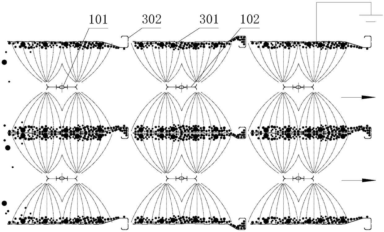
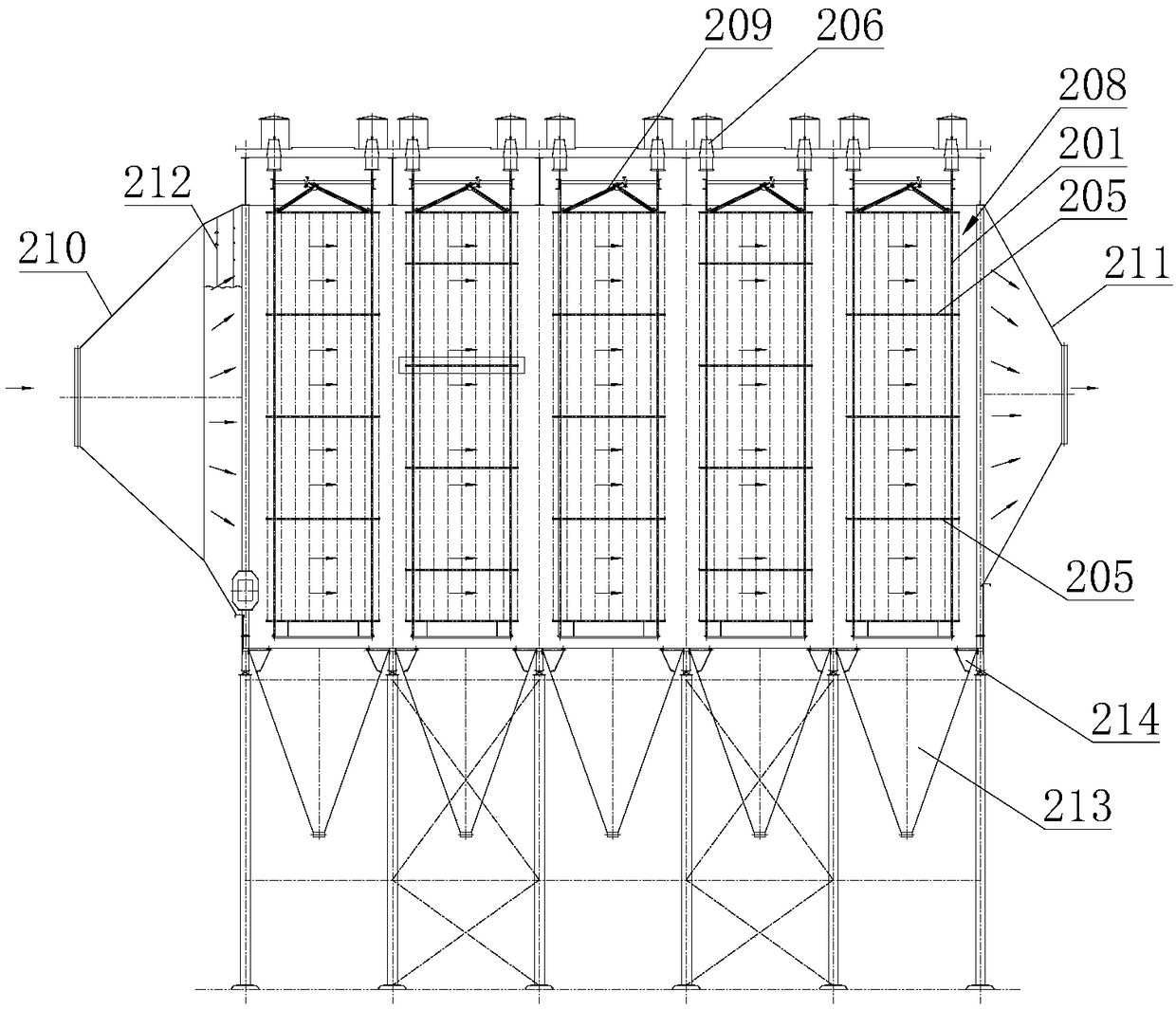
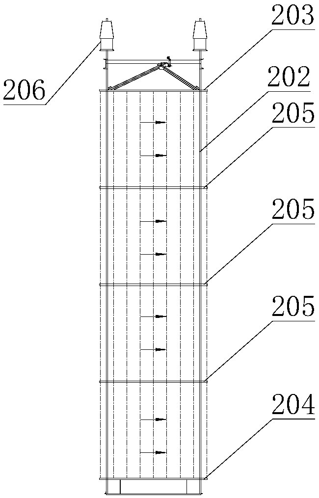
The invention discloses an efficient energy-saving type electric dust removing device which comprises cathode wires, cathode frameworks and anode plates. A plurality of cathode frameworks and a plurality of anode plates are arranged in parallel and in an alternating manner. A plurality of cathode wires are arranged in each cathode framework. Each cathode framework comprises a cross beam. The crossbeams of the cathode frameworks in two adjacent rows are not located on the same horizontal plane. Each cathode wire comprises a supporting pipe and a barb. The top end of each barb is provided witha front tip end and a rear tip end. The distance between each front tip end and the corresponding rear tip end is larger than the maximum distance between the front and the rear of each supporting pipe. The anode plates comprise a plurality of anode plate bodies. A collecting groove is formed in the right of each anode plate body, and a limiting edge is arranged on the left of each anode plate body. The electric dust removing device has the advantages that under the circumstance that dust-containing smoke close to the former electric field cathode framework cannot be charged, the dust-containing smoke enters the next electric field to be charged effectively, the shielding effect of corona discharge of the supporting pipes to the tip ends of the barbs can be effectively avoided, areas corresponding to the middle supporting pipes of the barb wires have corona currents, and the weight of the anode plates is reduced.

Description

technical field [0001] The invention relates to a high-efficiency and energy-saving electric dust collector. Background technique [0002] Electrostatic precipitator is the mainstream technology for dust removal in coal-fired thermal power plants, metallurgy, petrochemical and other fields, and the export of electrostatic precipitators can achieve 20mg / m 3 Even 15mg / m 3 The following stable emissions, but there are still disadvantages such as high energy consumption and the inability to efficiently charge particles under special flue gas conditions such as metallurgy. High efficiency and energy saving have become the mainstream development direction of electrostatic precipitators. At the same time, lighter weight and lower cost are also one of the development directions of electrostatic precipitators. [0003] At present, the mainstream pole matching types of electrostatic precipitators are "punched wire + 480C anode plate" and "acupuncture line + wave anode plate". Accord...

Claims


Application Information

Patent Timeline
Patent Type & Authority Applications(China)
IPC IPC(8): B03C3/43B03C3/47
CPCB03C3/43B03C3/47B03C2201/04
Inventor 赵海宝何毓忠赵金达冯国华傅潮
Owner 浙江菲达环保科技股份有限公司
Learn More