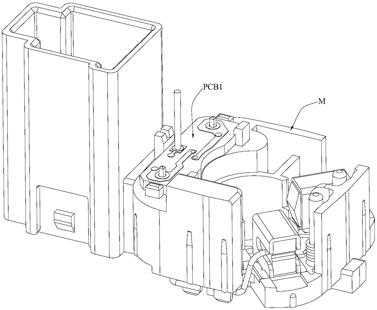
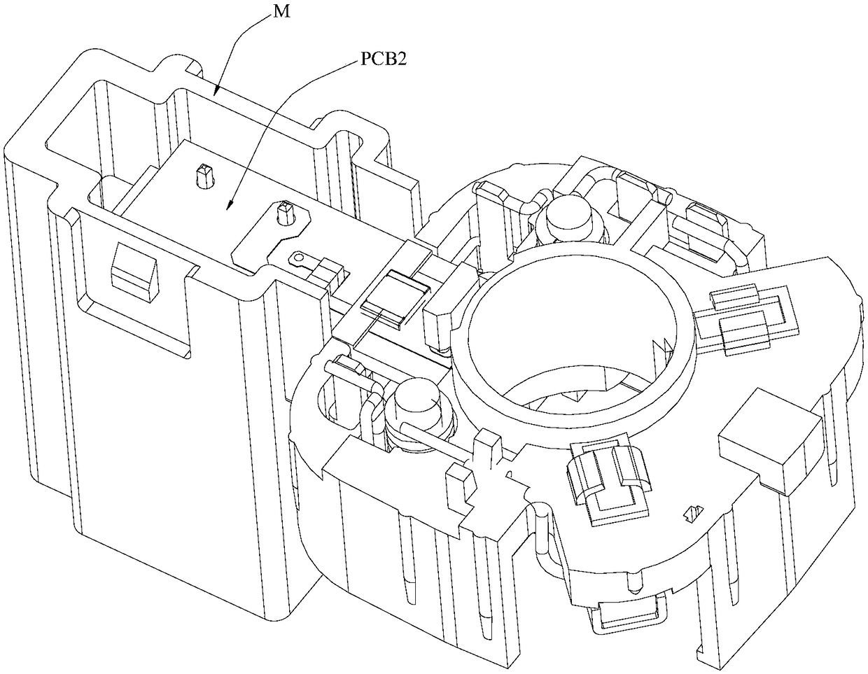
Front and reverse face welding device
A welding device, front and back technology, applied in auxiliary devices, welding equipment, metal processing, etc., can solve the problems of difficult to guarantee product consistency, low welding automation, low welding efficiency, etc., to reduce labor input and improve stability. Consistency with quality, the effect of improving efficiency and quality
- Summary
- Abstract
- Description
- Claims
- Application Information
AI Technical Summary
Problems solved by technology
Method used
Image
Examples
Embodiment 1
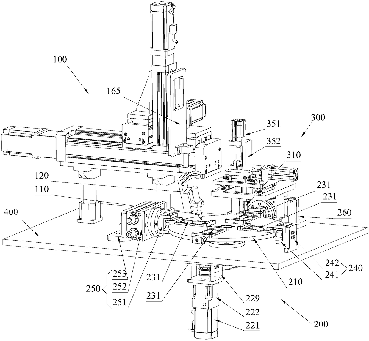
[0037] Such as figure 2 and image 3 As shown, the present invention discloses a front and back welding device, which is provided with a solder assembly 100, and the solder assembly 100 can weld the exposed position of the product to be welded;
[0038] The front and back welding device is also provided with a transposition assembly 200 and a workbench 400;
[0039] The transposition assembly 200 is provided with a turntable 210, a rotating drive mechanism 220, a turning mechanism 230, a loading and unloading station fixing mechanism 240 and a welding station turning driving mechanism 250;
[0040] The turning mechanism 230 is installed on the turntable 210, that is, the turntable 210 has an installation opening for each turning mechanism 230, and the turning mechanism 230 is provided with a jig 231 and a block 232. The jig 231 is suitable for fixing the product to be welded, the jig 231 is placed in the installation port, and the jig 231 is rotatably connected to the turntab...
Embodiment 2
[0052] On the basis of the first embodiment above, the second embodiment also adopts the following preferred structure:
[0053] The manner in which the jig 231 is rotatably connected to the turntable 210 is as follows: the mounting opening is a gap provided at the edge of the turntable 210; seat 235; the outer bearing seat 234 and the inner bearing seat 235 are respectively fixed on the turntable 210 by bolts and are respectively located on the outer side and the inner side of the installation port; the inner end of the outer rotating shaft 233 is connected to the jig The outer end of 231 is fixedly connected, the outer rotating shaft 233 is rotationally connected with the outer bearing seat 234, and the outer end of the outer rotating shaft 233 protrudes out of the turntable 210 and is fixedly connected with the block 232; The outer end of the inner rotating shaft is fixedly connected with the inner end of the jig 231 , and the inner end of the inner rotating shaft is rotati...
Embodiment 3
[0060] On the basis of the above-mentioned embodiment 1 or embodiment 2, this embodiment 3 also adopts the following preferred structure:
[0061] The front and back side welding device is also provided with a tin flying cleaning assembly 300, which can clean the tin flying on the exposed position of the welded product;
[0062] The transposition assembly 200 is also provided with a flipping drive mechanism 260 for the flying tin cleaning station; Composed of flying tin cleaning station fixing frame 263, the body of the flying tin cleaning station rotating power equipment 262 is fixed on the top surface of the workbench 400 by flying tin cleaning station fixing frame 263, and the flying tin cleaning station The rotary output shaft of the rotary power equipment 262 is connected and fixed to the flying tin cleaning station head 261, and the flying tin cleaning station head 261 is provided with a slot facing the turntable 210;
[0063] The rotation path of the turning mechanism ...
PUM
 Abstract
Description
Claims
Application Information
 - R&D
- Intellectual Property
- Life Sciences
- Materials
- Tech Scout
- Unparalleled Data Quality
- Higher Quality Content
- 60% Fewer Hallucinations
Browse by: Latest US Patents, China's latest patents, Technical Efficacy Thesaurus, Application Domain, Technology Topic, Popular Technical Reports.
© 2025 PatSnap. All rights reserved.Legal|Privacy policy|Modern Slavery Act Transparency Statement|Sitemap|About US| Contact US: help@patsnap.com


