
Manufacturing method of metal plate for power generating boiler supporting beam

A manufacturing method and technology for power generation boilers, applied in the direction of manufacturing tools, metal processing equipment, metal processing machinery parts, etc., can solve the problems of low recycling rate, poor debris collection effect, hindering normal processing, etc., and achieve recycling rate High, good debris collection effect, beneficial to the collection effect

Active Publication Date: 2019-01-29
武汉华电工程装备有限公司
View PDF6 Cites 1 Cited by
  • Summary
  • Abstract
  • Description
  • Claims
  • Application Information

AI Technical Summary

Problems solved by technology

[0006] The purpose of the present invention is to overcome the defects and problems existing in the prior art that hinder the normal processing, poor debris collection effect, and low recycling rate, and provide a recycling machine that is conducive to normal processing, good debris collection effect, and recycling. Manufacturing method of metal plate for supporting beam of power generation boiler with high utilization rate

Method used


Image

  • Manufacturing method of metal plate for power generating boiler supporting beam
  • Manufacturing method of metal plate for power generating boiler supporting beam
  • Manufacturing method of metal plate for power generating boiler supporting beam

Examples


Embodiment 1

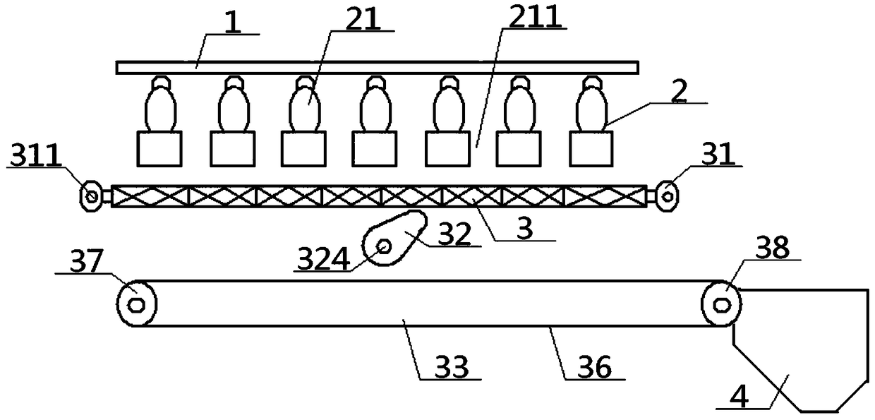
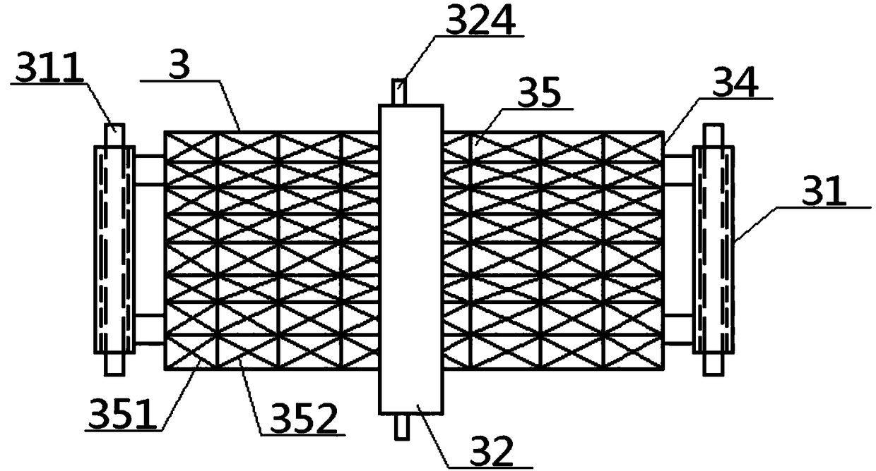
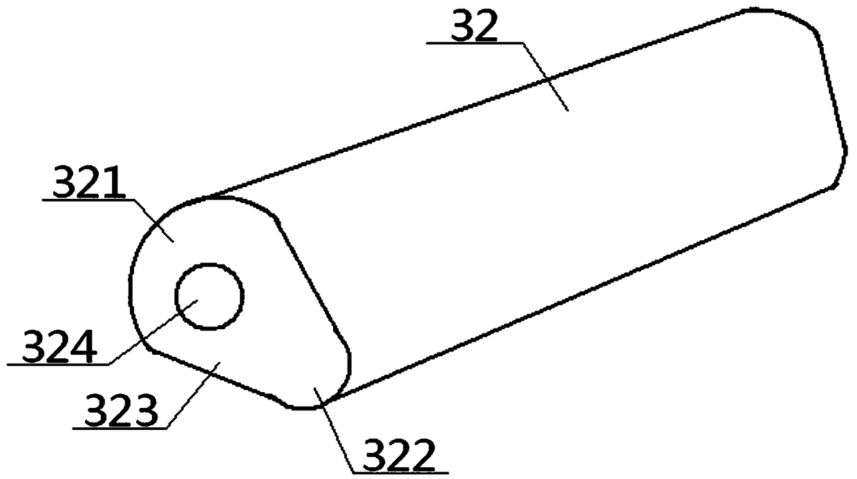
[0052] see Figure 1 to Figure 7 , a method for manufacturing a metal plate for a power boiler support beam, the manufacturing method includes the following steps: firstly place a metal plate 1 to be processed on a cutting unit 2, and the bottom surface of the metal plate 1 is supported by a strip in the cutting unit 2 The tops of the seats 21 are in contact, and the adjacent strip support seats 21 are provided with gaps 211 between the seats. , and then cut the sheet metal 1. During the cutting operation, the reciprocating sliding sleeve 31 relatively slides along the reciprocating sliding rod 311 to drive the trash net 3 to move back and forth. At the same time, the roller rotating rod 324 drives the upper bump The roller 32 rotates, and the roller rotating rod 324 reciprocates along the horizontal direction, and the rotating upper bump roller 32 lifts and lowers the trash net 3 above it at intervals, so that the trash net 3 moves up and down, back and forth The moving, up ...

Embodiment 2

[0055] Basic content is the same as embodiment 1, the difference is:

[0056] The miscellaneous device 33 includes a miscellaneous crawler belt 36, a left miscellaneous roller 37 and a right miscellaneous roller 38, and the two ends of the miscellaneous crawler belt 36 are respectively wrapped around the rollers of the left miscellaneous roller 37 and the right miscellaneous roller 38. On the surface, a plurality of miscellaneous partition strips 361 are uniformly arranged on the outer surface of the miscellaneous crawler 36, and the bottom of the miscellaneous partition strip 361 is vertically connected with the outer surface of the miscellaneous crawler 36, and the adjacent miscellaneous partition strips 361 are parallel to each other, and the adjacent miscellaneous partition strips 361 and the miscellaneous track 36 between them constitute a miscellaneous box 362 . Preferably, on the crawler belt 36 for carrying miscellaneous materials, the inside and outside sides of the p...

Embodiment 3

[0058] Basic content is the same as embodiment 1, the difference is:

[0059] The recovery unit 4 includes a recovery upper baffle plate 41, a reclaimed outer baffle plate 42, a recovery left lower slant baffle plate 43 and a recovery right lower slant baffle plate 44. Shaped plate structure, and the arc-shaped protrusions of the recovered left lower inclined baffle 43 and the recovered right lower inclined baffle 44 are facing to each other; the top of the recovered left lower inclined baffle 43 is hinged with the bottom end of the tail sweeping air pipe 431, The top air outlet of the tail sweeping air pipe 431 is arranged near the bottom surface of the outer end of the right miscellaneous roller 38, and the top surface of the outer end of the right miscellaneous roller 38 is set near the inner end of the recovery upper baffle plate 41, and the outer end of the upper baffle plate 41 is reclaimed with the The top of reclaiming the outer baffle 42 is vertically connected, and t...


PUM


Abstract

The invention discloses a manufacturing method of a metal plate for a power generating boiler supporting beam. When in applying, firstly, the metal plate to be machined is placed on a cutting unit, the bottom face of the metal plate is in contact with the top end of a strip-shaped supporting base in the cutting unit, then cutting operation is carried out on the metal plate, and the reciprocating sliding sleeve slides along a reciprocating sliding rod to do relative motion, so that an impurity falling net is drove to move forwards and backwards while the cutting is carried out at the same time;a roller rotating rod drives an upper ejecting convex block roller to rotate and do reciprocating motion along the horizontal direction; the rotating upper ejecting convex block roller upwards ejected and downwards fallen at intervals the impurity falling net positioned above the rotating upper ejecting convex block roller, so that the impurity falling net can move up and down; and the impurity falling net which moves front and back as well as up and down is used for continuously vibrating metal chippings which fall on the impurity falling net in the cutting operation, the metal chippings areenable to fall onto an impurity conveying device after passing through the impurity falling net, and then the metal chippings are conveyed to a recycling unit to be recycled through the impurity conveying device. According to the method, the metal chippings collecting effect is good, and the recycling rate is relatively high as well.

Description

technical field [0001] The invention relates to a method for manufacturing a special metal plate for power generation equipment, in particular to a method for manufacturing a metal plate for a supporting beam of a power generation boiler. Background technique [0002] Existing thermal power plants need to use a large number of steel structures, such as tower crane shells, power boiler brackets, pipe trusses, etc. Among them, H-shaped and Tian-shaped beams are the most common. In the process of manufacturing these beams In the process, it is necessary to perform blanking, shearing, small plate drilling, welding, straightening, grinding or painting on the original plate. Among them, the plate must be cut during blanking and shearing. [0003] In the prior art, when blanking, shearing or punching small plates, cutting operations are required, and the cutting methods include CNC plasma cutting, CNC flame cutting, CNC hydraulic cutting, and CNC aurora cutting. When cutting, the ...

Claims


Application Information

Patent Timeline
Patent Type & Authority Applications(China)
IPC IPC(8): B23Q11/00
Inventor 龚敏熊睿赵聪文化黄良柱
Owner 武汉华电工程装备有限公司
Learn More