Spinning machine with high safety

A high-safety, textile machine technology, applied in the direction of continuous winding spinning machine, textile, loom, etc., can solve the problems of poor versatility, adaptation, damage of anti-pinch device, etc. Good performance and stability

Inactive Publication Date: 2019-01-29
周芹花
View PDF1 Cites 1 Cited by
  • Summary
  • Abstract
  • Description
  • Claims
  • Application Information

AI Technical Summary

Problems solved by technology

Therefore, anti-trap is not realized in the true sense
At the same time, because the ball is in the environment of continuous beating and friction with the semicircular groove, it is very easy to cause damage to the anti-pinch device
[0004] 2. This anti-clamping device cannot be adapted to different sizes of motor output ends and power receiving ends of the shaft, and can only choose fixed-size motor output shafts and shafts, which leads to poor versatility and cannot adapt to different models
[0005] 3. It is well known that existing textile machines have different installation heights of motors and shafts for different types of textile machines, and the above-mentioned anti-pinch device does not have the ability to adjust the height, which also leads to poor versatility and is not convenient for existing Some models are modified

Method used


Image

  • Spinning machine with high safety
  • Spinning machine with high safety
  • Spinning machine with high safety

Examples


Embodiment Construction

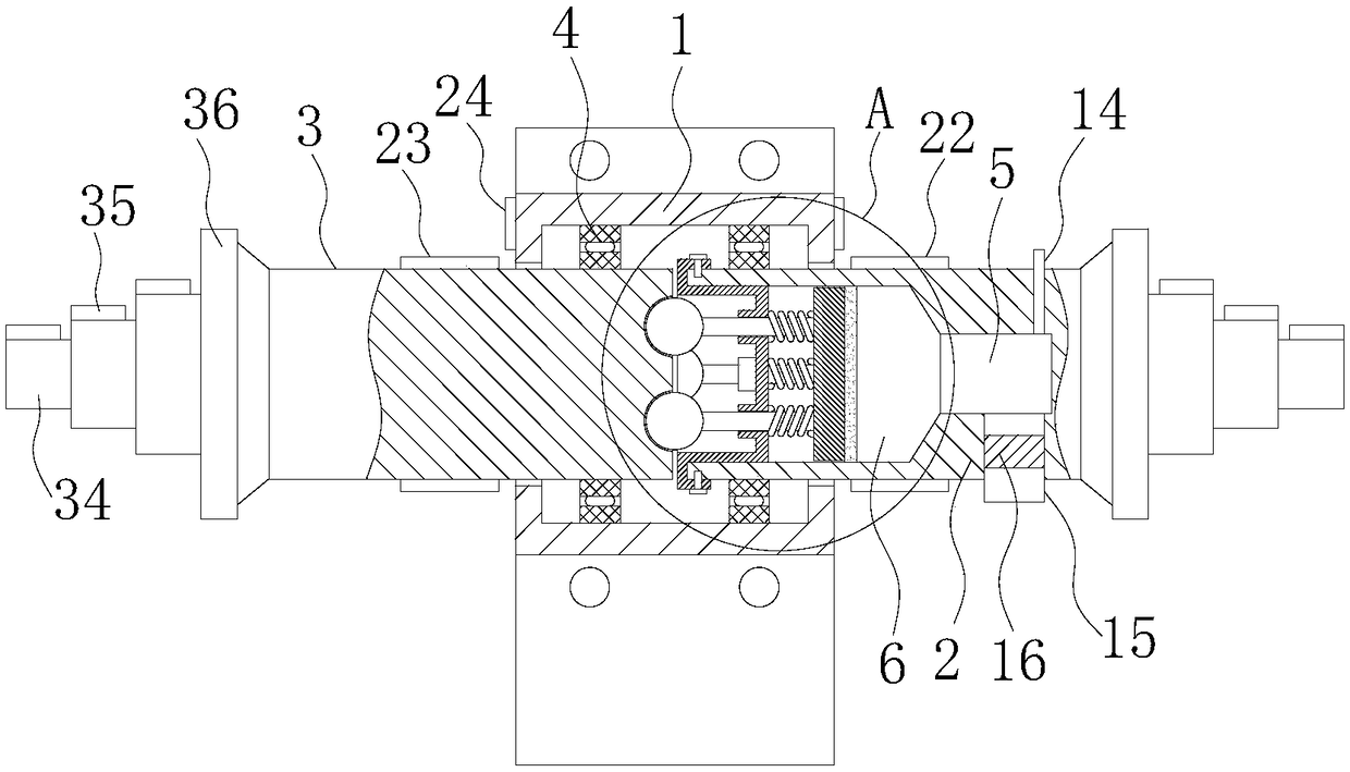
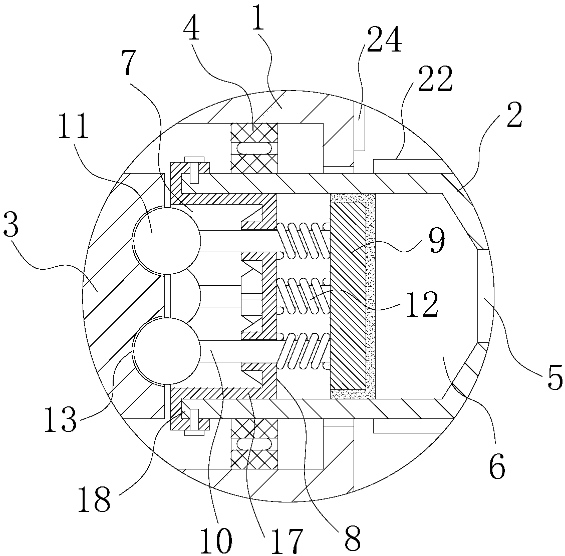
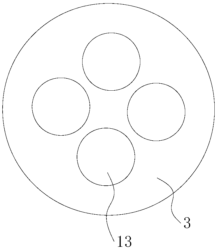
[0024] like Figure 1-6 A textile machine with high safety is shown, the power transmission path between the prime mover and the shaft of the textile machine is provided with an anti-pinch device, and the prime mover can be an oil extraction machine, a gasoline engine, an electric motor, etc. , generally using a motor; the shaft is the shaft that uses power, such as the conveyor shaft, reel, wheel shaft, etc. of the textile machine. The anti-pinch device of the present invention is used to connect the motor and the shaft, transmit the power of the motor to the shaft, and perform abnormal protection. like figure 1 As shown, the anti-pinch device includes a mounting base 1 and a main shaft 2 and a sub shaft 3 with opposite ends. The mounting seat 1 is in the shape of a sleeve, which is set on the opposite side of the main shaft 2 and the auxiliary shaft 3, and is respectively connected with the main shaft 2 and the auxiliary shaft 3 through the bearing 4, and the opposite ends...


PUM

PropertyMeasurementUnit
diameteraaaaaaaaaa

Abstract

The invention relates to the technical field of spinning, and aims at providing a spinning machine with high safety and high universality. According to the technical scheme, in the spinning machine with high safety, a clamping prevention device is arranged on a power transmission path between a prime motor and an application shaft of the spinning machine and includes a mounting base, a main shaftand an auxiliary shaft, wherein one end of the main shaft is opposite to one end of the auxiliary shaft; the mounting base sleeves the portion where the main shaft and the auxiliary shaft are oppositeand is connected with the main shaft and the auxiliary shaft through bearings, and connection sections for being in transmission connection with the prime motor and the application shaft are arrangedat the reverse ends of the main and auxiliary shafts respectively; the connection sections gradually diminish in the direction away from the mounting base and are composed of three-grade connection parts distributed in a stair mode, and a connection protrusion key is arranged on each grade of the connection parts. By adopting the spinning machine with high safety and high universality, gears of different specifications can be mounted on the three-grade connection parts of the connection sections, therefore, the spinning machine can be better matched with motor output shafts of different typesand application shafts of different types, and the universality is high.

Description

technical field [0001] The invention relates to the technical field of textiles, in particular to a textile machine with high safety. Background technique [0002] Textile machine is exactly the general term of the tool that weaves cloth into cloth after raw material such as thread, silk, fiber crops is processed into silk thread. Modern textile machinery uses mechanical technology, electrical technology, and weak current technology to create a wide variety of processing machines with different performances, which greatly improves the output of textile machinery. Generally speaking, modern textile machines mainly rely on the prime mover (generally a motor) to run at high speed under the coordination of the controller, and the output end of the prime mover drives mechanical devices such as reels and conveying shafts for production. Although the overall performance of textile machinery is getting better and better, there are still certain defects, such as once foreign matter ...

Claims


Application Information

Patent Timeline
Patent Type & Authority Applications(China)
IPC IPC(8): D01H1/24D03D51/02
CPCD01H1/24D03D51/02
Inventor 周芹花
Owner 周芹花
Why Eureka
Try Eureka