Cloth cutting bed

A cloth cutting and outer surface technology, which is applied in the field of cutting bed, can solve the problems that thin threads are easily inhaled into the body, the area of ​​the cutting bed is large, and the effect of cutting cloth is affected, so as to prevent the cloth cutting effect from being good and avoid the body Discomfort, the effect of ensuring physical health

Inactive Publication Date: 2019-01-29
阜阳鑫合服饰有限公司
View PDF4 Cites 2 Cited by
  • Summary
  • Abstract
  • Description
  • Claims
  • Application Information

AI Technical Summary

Problems solved by technology

[0002] Cloth cutting bed is a common operating table for people to handle cloth, clothing, leather and other items. It is usually used in factories that cut cloth by hand. With the development of society, people's consumption level continues to increase. For various The demand for fabrics is also increasing. In order to speed up people's processing of fabrics, people have invented many tools related to fabric cutting, among which are cutting beds. With the continuous development of science and technology, people's requirements for cutting beds It is also getting higher and higher, causing the existing cutting bed to fail to meet

Method used


Image

  • Cloth cutting bed
  • Cloth cutting bed
  • Cloth cutting bed

Examples


Embodiment 1

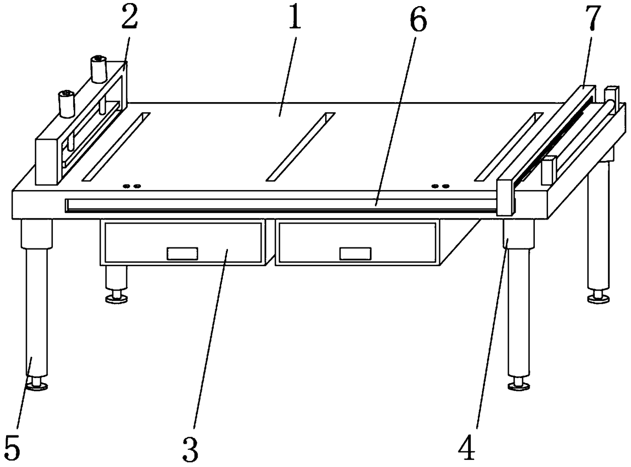
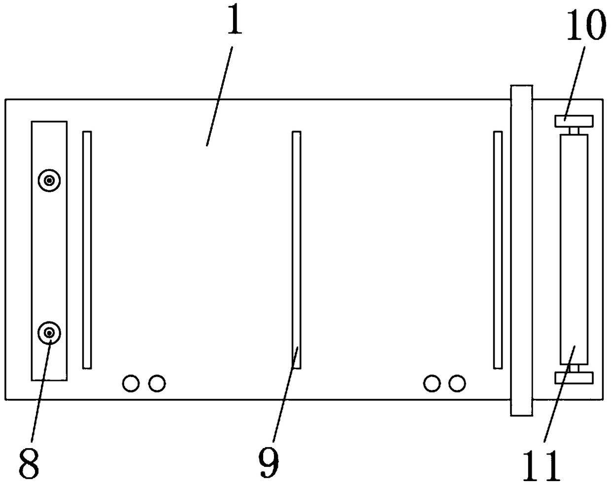
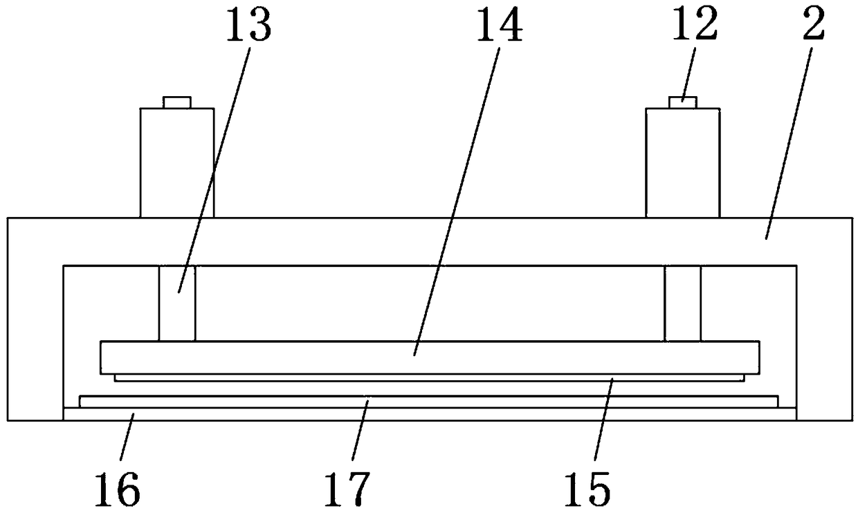
[0028] Such as Figure 1-5 As shown, a cutting bed includes a main body 1 of the cutting bed. A fixing frame 2 is fixedly installed on the outer surface of the upper end of the main body 1 of the cutting bed near one side. A set of drawers 3, a shock absorber 4 is fixedly installed on the outer surface of the lower end of the main body of the cutting bed 1 close to the four corners, and a support column 5 is fixedly installed on the outer surface of the lower end of the shock absorber 4. The surfaces are all provided with sliding grooves 6, and the outer surface of the front end of the main body of the cutting bed 1 is provided with a movable frame 7 on the side away from the fixed frame 2, and the outer surface of the upper end of the main body of the cutting bed 1 is provided with three sets of strip grooves 9. The outer surface of the upper end of the main body 1 is provided with two sets of fixed plates 10 on the side close to the movable frame 7. Bearings are fixedly inst...

Embodiment 2

[0032] Such as Figure 1-5 As shown, a cutting bed includes a main body 1 of the cutting bed. A fixing frame 2 is fixedly installed on the outer surface of the upper end of the main body 1 of the cutting bed near one side. A set of drawers 3, a shock absorber 4 is fixedly installed on the outer surface of the lower end of the main body of the cutting bed 1 close to the four corners, and a support column 5 is fixedly installed on the outer surface of the lower end of the shock absorber 4. The surfaces are all provided with sliding grooves 6, and the outer surface of the front end of the main body of the cutting bed 1 is provided with a movable frame 7 on the side away from the fixed frame 2, and the outer surface of the upper end of the main body of the cutting bed 1 is provided with three sets of strip grooves 9. The outer surface of the upper end of the main body 1 is provided with two sets of fixed plates 10 on the side close to the movable frame 7. Bearings are fixedly inst...

Embodiment 3

[0037] Such as Figure 1-5 As shown, a cutting bed includes a main body 1 of the cutting bed. A fixing frame 2 is fixedly installed on the outer surface of the upper end of the main body 1 of the cutting bed near one side. A set of drawers 3, a shock absorber 4 is fixedly installed on the outer surface of the lower end of the main body of the cutting bed 1 close to the four corners, and a support column 5 is fixedly installed on the outer surface of the lower end of the shock absorber 4. The surfaces are all provided with sliding grooves 6, and the outer surface of the front end of the main body of the cutting bed 1 is provided with a movable frame 7 on the side away from the fixed frame 2, and the outer surface of the upper end of the main body of the cutting bed 1 is provided with three sets of strip grooves 9. The outer surface of the upper end of the main body 1 is provided with two sets of fixed plates 10 on the side close to the movable frame 7. Bearings are fixedly inst...


PUM


Abstract

The invention discloses a cloth cutting bed which comprises a cloth cutting bed body. A fixing frame is fixedly arranged at the position, close to one side, of the outer surface of the upper end of the cloth cutting bed body; two sets of drawers are arranged in the middle of the outer surface of the lower end of the cloth cutting bed body, and shock absorbers are fixedly installed at the positions, close to the four corners, of the outer surface of the lower end of the cloth cutting bed body; the outer surfaces of the lower ends of the shock absorbers are fixedly provided with supporting columns. According to the cloth cutting bed, cloth can be conveniently fixed by people, the speed for fixing the cloth is relatively high, and the cloth cutting efficiency is improved; people can conveniently clean away dust on the surface of the cloth cutting bed, and the cleaning effect is good; finally, tiny substances such as cloth and fluff which are caused by cutting the cloth can be sucked intoan ash storage box, so that the body discomfort caused when an operator inhales the micro cloth is avoided, the body health of the operator is guaranteed, and better application prospects are brought.

Description

technical field [0001] The invention relates to the field of cutting beds, in particular to a cutting bed. Background technique [0002] Cloth cutting bed is a common operating table for people to handle cloth, clothing, leather and other items. It is usually used in factories that cut cloth by hand. With the development of society, people's consumption level continues to increase. For various The demand for fabrics is also increasing. In order to speed up people's processing of fabrics, people have invented many tools related to fabric cutting, among which are cutting beds. With the continuous development of science and technology, people's requirements for cutting beds It is also getting higher and higher, causing the existing cutting bed to fail to meet the requirements of people; [0003] There are certain disadvantages in the use of the existing cutting bed. First, the existing cutting bed usually adopts manual fixing of the position of the cloth. The fixing time is re...

Claims


Application Information

Patent Timeline
IPC IPC(8): D06H7/00B08B1/00B26D7/18
CPCB08B1/002B26D7/1863D06H7/00
Inventor 黄祖运
Owner 阜阳鑫合服饰有限公司
Why Eureka
Try Eureka