Flashing structure of building roof parapet and construction method

A roof structure layer and parapet technology, which is applied to building structures, roofs, buildings, etc., can solve problems such as cracking, waterproof failure, and waterproof membrane swelling, and achieve simple construction steps, enhanced tensile properties, and easy operation Effect

Pending Publication Date: 2019-01-29
WUHAN CONSTR ENG
View PDF0 Cites 4 Cited by
  • Summary
  • Abstract
  • Description
  • Claims
  • Application Information

AI Technical Summary

Problems solved by technology

During the long-term use of the flashing structure made by this construction method, due to the large difference in temperature expansion coefficient between the reinforced concrete structure roof and the brick masonry flashing structure, the flashing wall (parapet) is easy to crack, and the flashing Cracks in the water wall will cause the waterproof membrane to bulge, crack, and fall off, which will eventually lead to waterproof failure and roof leakage
At the same time, the protective layer is attached to the smooth surface of the waterproof membrane, the adhesion between the protective layer and the waterproof membrane is insufficient, the protective layer is easy to crack, fall off, and loses its protective effect, so that the waterproof membrane is exposed. The aging of the waterproof membrane is accelerated and gradually loses its waterproof effect. Therefore, the industry needs a construction method for building roof parapets to solve the problem that the waterproof membrane is easy to bulge, crack, and fall off, which eventually leads to waterproof failure.

Method used


Image

  • Flashing structure of building roof parapet and construction method
  • Flashing structure of building roof parapet and construction method
  • Flashing structure of building roof parapet and construction method

Examples


Embodiment Construction

[0025] The present invention will be further described below in conjunction with the accompanying drawings.

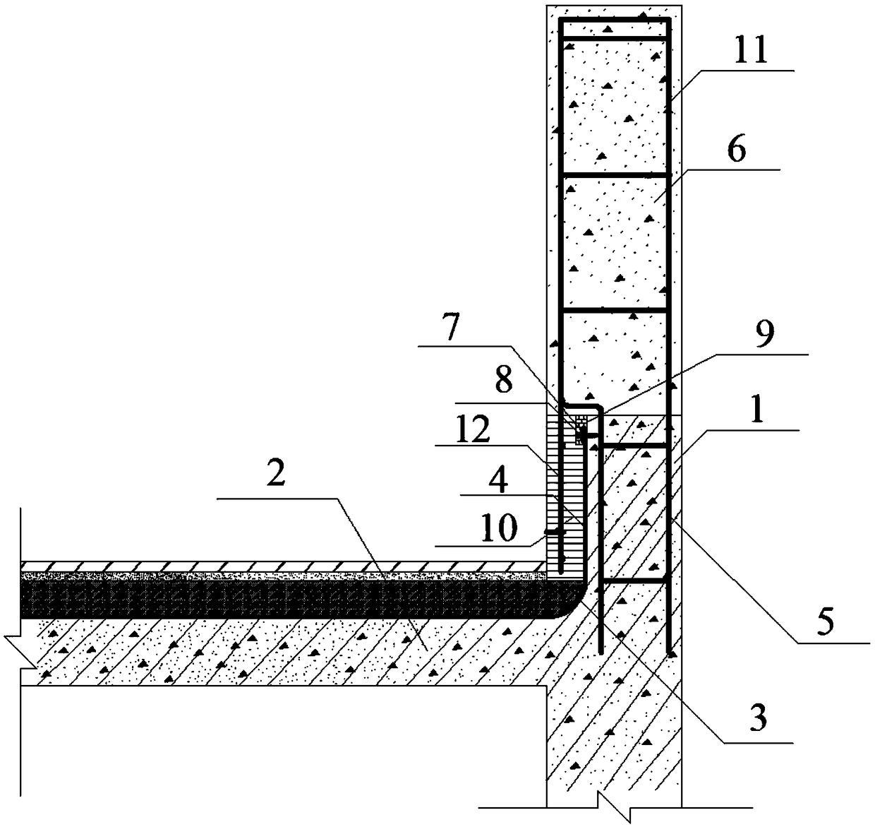
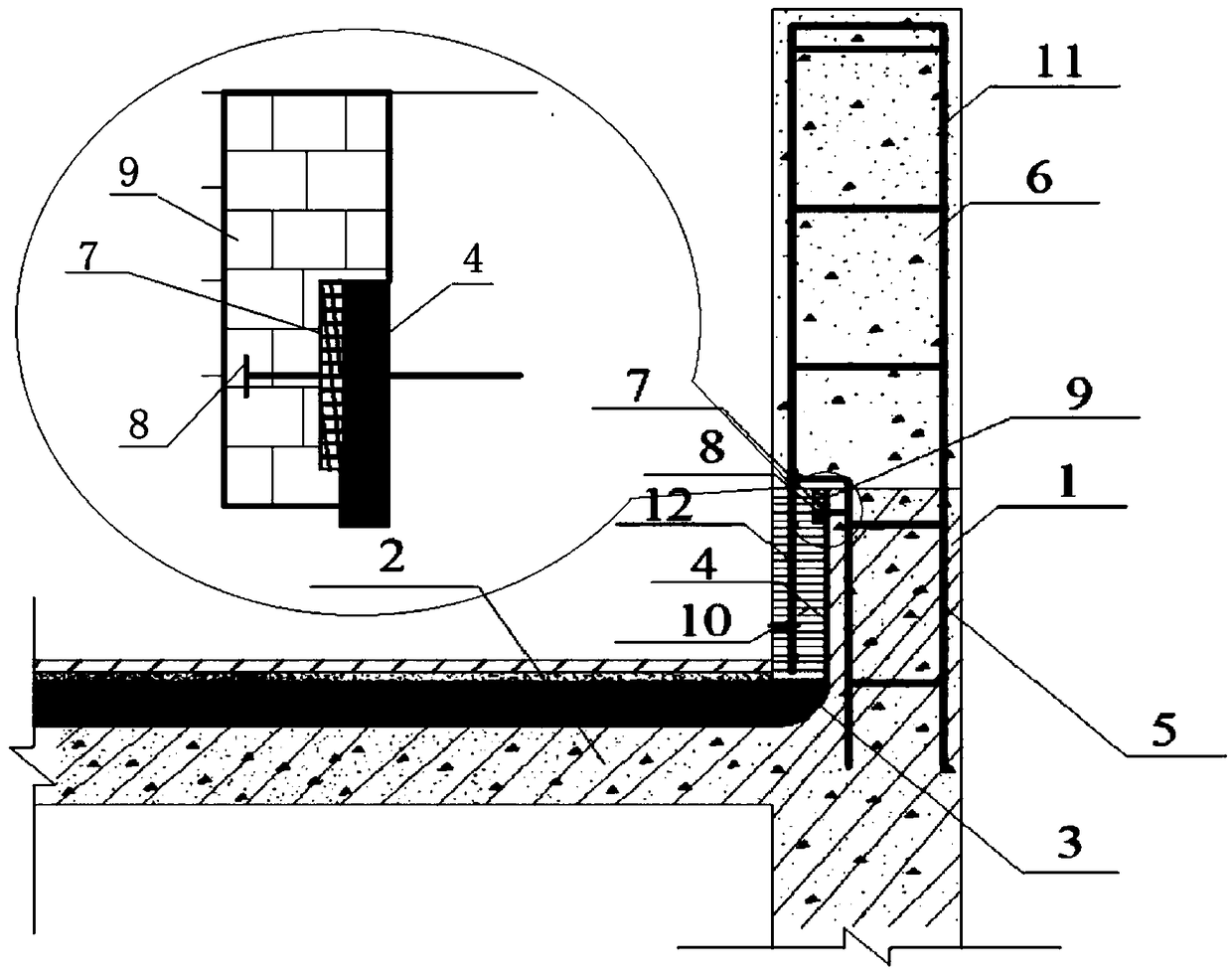
[0026] Such as figure 1 As shown, the building roof parapet flashing structure includes the first steel bar frame vertically arranged in the building roof structure layer 2, and the flashing wall body 1 integrated with the building roof structure layer 2 is poured on the outside of the building roof structure layer 6 The waterproof protective layer 10 of reinforced concrete structure, the flashing wall 1 is a reinforced concrete structure, on the top surface of the flashing wall 1, the parapet 6 and the flashing wall 1 pass through the internal The reinforcement structure of the parapet body 6 is thicker than the flashing wall body 1, and the vertical waterproof protective layer 10 is extended downward based on the bottom of the parapet body body 6 away from the side of the flashing wall body 1, so The upper surface of the roof structure layer 2 of the building and th...


PUM


Abstract

The invention relates to a building roof parapet. The building roof parapet comprises a flashing wall body integrated with a building roof structural layer and a waterproof protective layer of a reinforced concrete structure poured on the outer side of a parapet body, wherein on the top surface of the flashing wall body, the parapet body and the flashing wall body are connected through an internally arranged rebar structure, the thickness of the parapet body is larger than that of the flashing wall body, and the bottom of the side, away from the flashing wall body, of the parapet body is takenas a base and extends downwards out of the vertical waterproof protective layer; and waterproof coiled materials are paved on the building roof structural layer and the inner elevation of the flashing wall body, the waterproof coiled materials are pressed on the flashing wall body through metal battens and steel nails, and gaps between the top edge of the waterproof coiled materials and the innerelevation of the flashing wall body are filled with sealants. According to the building roof parapet, the tensile property of the waterproof protective layer and the integral property of the waterproof protective layer and the parapet are enhanced, and the situation that the protective effect is lost caused by cracking and falling off due to insufficient bonding force between the waterproof protective layer and the waterproof coiled material is avoided.

Description

technical field [0001] The invention relates to the technical field of architectural engineering construction decoration, relates to a building roof parapet flooding structure, and more particularly relates to a construction method for a building roof parapet flooding structure. Background technique [0002] Roof parapet flashing refers to the waterproof structure between the roof waterproof layer and the parapet, and the junction of the roof parapet surface and the roof extends the roof waterproof layer to these vertical surfaces to form a vertical waterproof structure. At present, the construction method of building roof parapet flooding is as follows: build a brick masonry parapet on the reinforced concrete structure roof, then lay a waterproof membrane on the parapet as a waterproof layer, and brush a layer on the waterproof membrane Mortar acts as a protective layer for the waterproofing. During the long-term use of the flashing structure made by this construction meth...

Claims


Application Information

Patent Timeline
Patent Type & Authority Applications(China)
IPC IPC(8): E04D13/14
CPCE04D13/1415
Inventor 夏进胡宝明李文祥王文玮杜峰孔宪勇王聪
Owner WUHAN CONSTR ENG
Why Eureka
Try Eureka