Sensitive equipment fault rate calculation method and device
A technology of sensitive equipment and calculation method, which is applied in the field of data communication and can solve the problems of large calculation error and inability to objectively and accurately calculate the failure rate of sensitive equipment.
- Summary
- Abstract
- Description
- Claims
- Application Information
AI Technical Summary
Problems solved by technology
Method used
Image
Examples
Embodiment 1
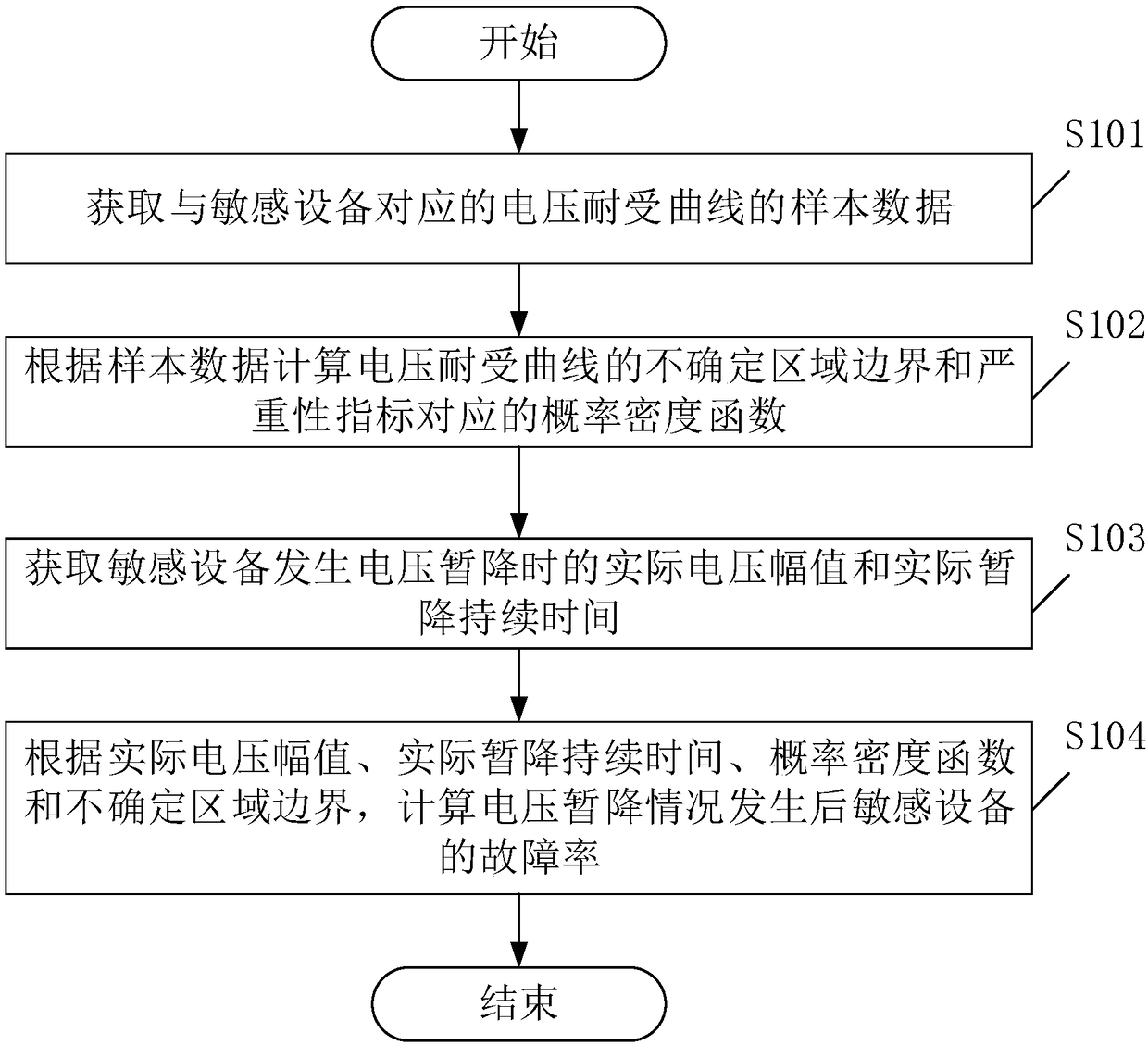
[0071] see figure 1 , figure 1 It is a schematic flowchart of a calculation method for the failure rate of sensitive equipment provided by an embodiment of the present invention. Among them, such as figure 1 As shown, the calculation method of the failure rate of the sensitive equipment may include the following steps:
[0072] S101. Obtain sample data of a voltage withstand curve corresponding to a sensitive device.
[0073] In this embodiment, a sensitive device is a general term for an object to be disturbed in an electrical system, and may be a small electronic component, a circuit board assembly, a single electrical device, or even a large system. Specifically, sensitive devices can be frequency converters (Variable-frequency Drive, VFD), motors, contactors, adjustable speed drives (adjustable speed drives, ASD), programmable logic controllers (programmable logic controllers, PLC) and personal computers ( personal computer, PC), etc., which is not limited in this embo...
Embodiment 2
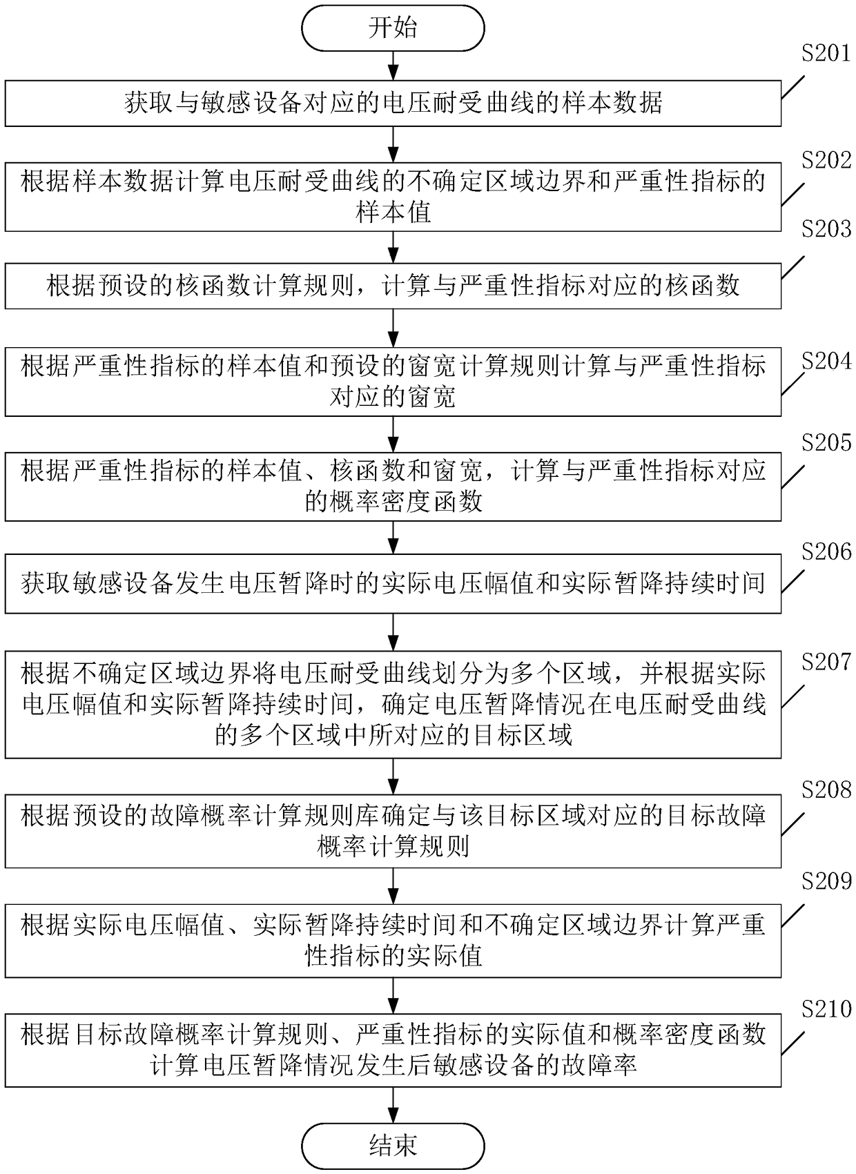
[0084] see figure 2 , figure 2 It is a schematic flowchart of a calculation method for the failure rate of sensitive equipment provided by an embodiment of the present invention. Among them, such as figure 2 As shown, the calculation method of the failure rate of the sensitive equipment may include the following steps:
[0085] S201. Obtain sample data of a voltage withstand curve corresponding to a sensitive device.
[0086] S202. Calculate the boundary of the uncertainty region of the voltage withstand curve and the sample value of the severity index according to the sample data.
[0087] In this embodiment, the calculation formula for calculating the boundary of the uncertain region of the voltage withstand curve according to the sample data is:
[0088] u max =max{U 1 , U 2 ,...,U n};
[0089] u min =min{U 1 , U 2 ,...,U n};
[0090] T max =max{T 1 ,T 2 ,...,T n};
[0091] T min =min{T 1 ,T 2 ,...,T n};
[0092] Among them, U min is the upper boun...
Embodiment 3
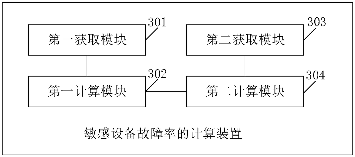
[0157] see image 3 , image 3 It is a structural schematic diagram of a calculation device for the failure rate of sensitive equipment provided by an embodiment of the present invention. Among them, such as image 3 As shown, the calculation device for the failure rate of the sensitive equipment includes:
[0158] The first acquisition module 301 is configured to acquire sample data of a voltage withstand curve corresponding to sensitive equipment.
[0159] The first calculation module 302 is configured to calculate the probability density function corresponding to the boundary of the uncertain region of the voltage withstand curve and the severity index according to the sample data.
[0160] The second acquiring module 303 is configured to acquire the actual voltage amplitude and the actual duration of the voltage sag when the sensitive device has a voltage sag.
[0161] The second calculation module 304 is configured to calculate the failure rate of the sensitive equipm...
PUM
 Abstract
Description
Claims
Application Information
 - R&D
- Intellectual Property
- Life Sciences
- Materials
- Tech Scout
- Unparalleled Data Quality
- Higher Quality Content
- 60% Fewer Hallucinations
Browse by: Latest US Patents, China's latest patents, Technical Efficacy Thesaurus, Application Domain, Technology Topic, Popular Technical Reports.
© 2025 PatSnap. All rights reserved.Legal|Privacy policy|Modern Slavery Act Transparency Statement|Sitemap|About US| Contact US: help@patsnap.com


