Dust removing mechanism of side wall type plate placing machine

A technology for placing boards and sticking dust, which is applied in the direction of cleaning methods using gas flow, cleaning methods and utensils, chemical instruments and methods, etc., can solve the problems of difficult removal of foreign matter on the surface of boards and weakening of the effect of sticky dust sheets, and achieve Improve cleanliness and uniform blowing force

Pending Publication Date: 2019-02-01
大江南电子科技(昆山)有限公司
View PDF1 Cites 5 Cited by
  • Summary
  • Abstract
  • Description
  • Claims
  • Application Information

AI Technical Summary

Problems solved by technology

[0004] However, when the sticky dust machine is working, the sticky dust sheet is driven by the transmission device to rotate repeatedly in the circumferential direction. After a long time of use, the effect of the sticky dust sheet will gradually weaken, and it is difficult to remove foreign matter on the surface of the board.

Method used


Image

  • Dust removing mechanism of side wall type plate placing machine
  • Dust removing mechanism of side wall type plate placing machine
  • Dust removing mechanism of side wall type plate placing machine

Examples


Embodiment

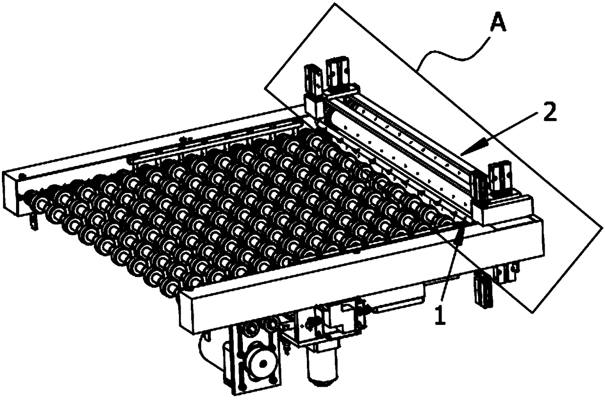
[0040] Embodiment: a kind of dust removal mechanism of side wall type board machine, such as Figure 1-Figure 7 As shown, it includes a dust removal mechanism fixed on the frame, and the dust removal mechanism includes a primary dust blowing structure 1 and a secondary dust sticking structure 2 symmetrically located downstream of the conveying section, and the primary dust blowing structure 1 is located at the second Upstream of Class Sticky Structure 2;

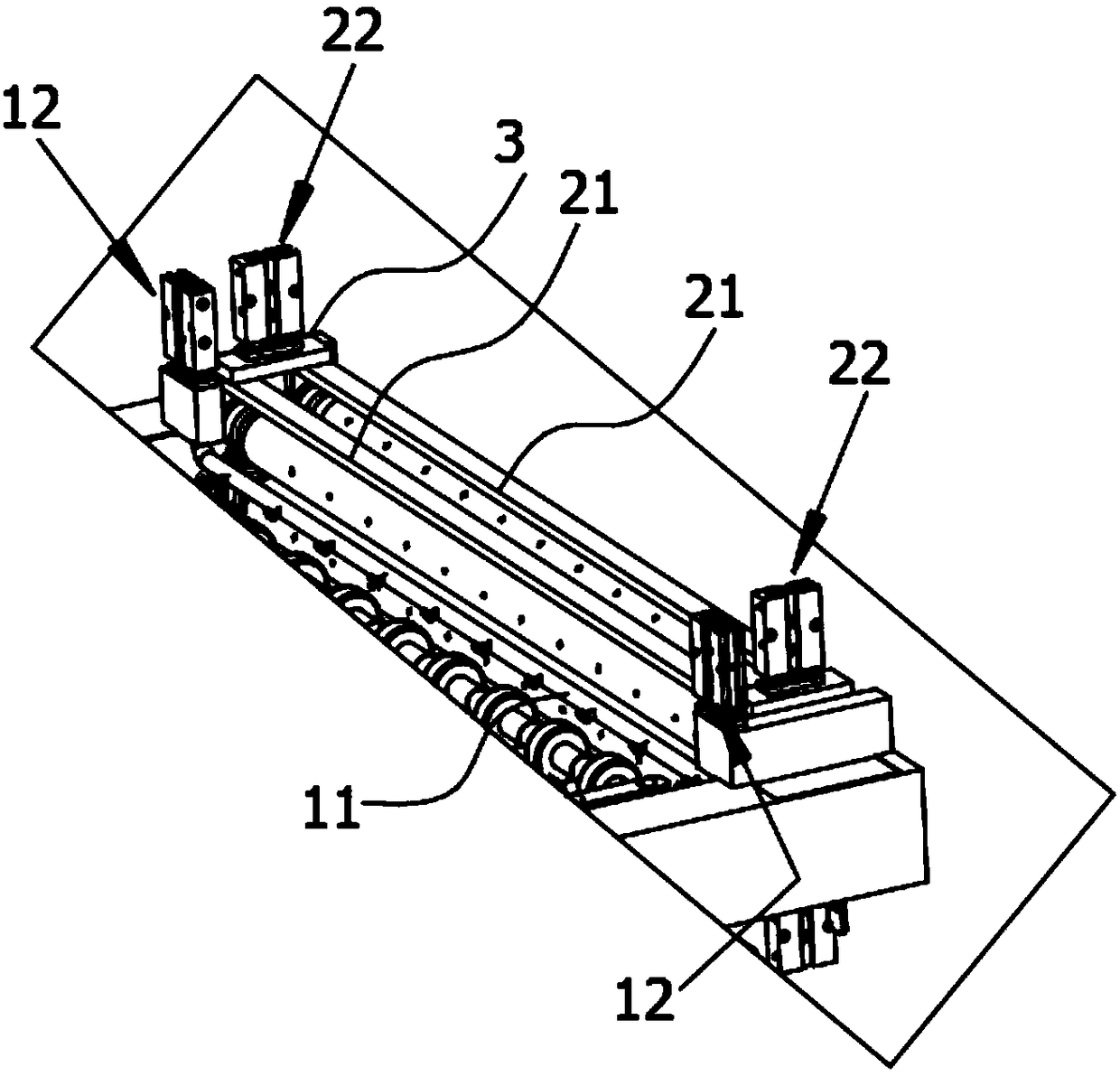
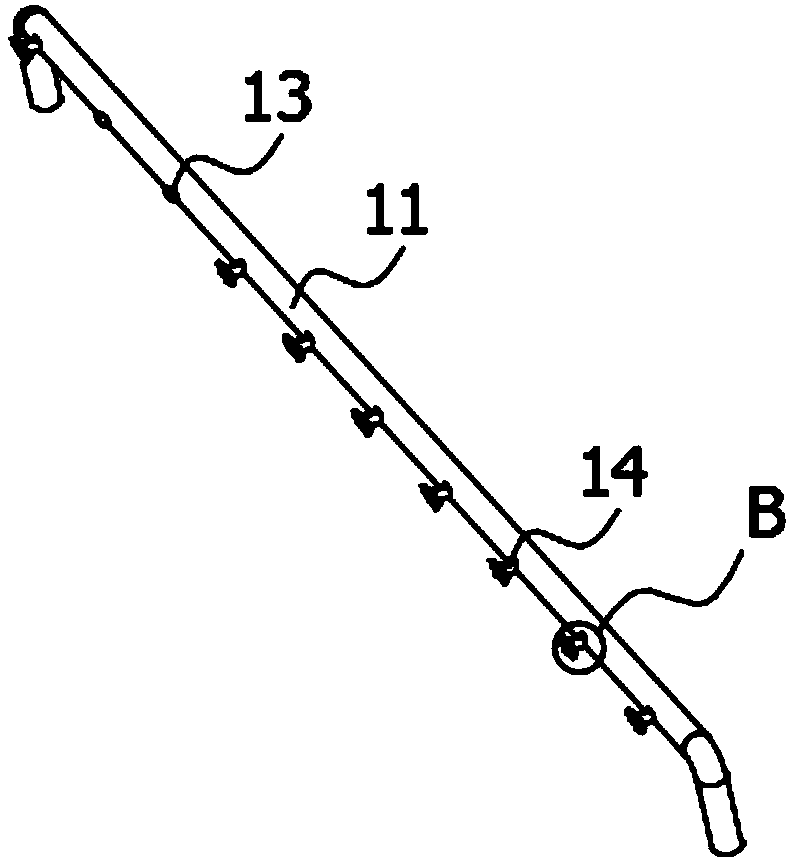
[0041] Each of the first-stage dust blowing structures 1 includes a hollow tube 11 and a first lifting structure 12 that drives the hollow tube close to and away from the conveying section, and the space between the two hollow tubes that are symmetrical up and down is the gap through which the material passes; One end of the hollow tube 12 is closed and the other end is connected to the gas source through a trachea. The side of the hollow tube 12 opposite to the material conveying direction is evenly distributed with through...


PUM


Abstract

The invention discloses a dust removing mechanism of a side wall type plate placing machine. The dust removing mechanism of the side wall type plate placing machine comprises first-stage dust blowingstructures and second-stage dust sticking structures, wherein the first-stage dust blowing structures and the second-stage dust sticking structures are symmetrically positioned on the downstream of aconveying section; each first-stage dust blowing structure comprises a hollow circular tube and a first lifting structure used for driving the corresponding hollow circular tube to be close to or awayfrom the conveying section; and each two-stage dust sticking structure comprises at least two dust sticking rollers, a second lifting structure used for driving the dust sticking rollers to be closeto / away from the conveying section, and hollow rotating shafts arranged inside the dust sticking rollers in a sleeved mode, wherein one ends of the hollow rotating shafts are provided with air extracting openings, the other ends of the hollow rotating shafts are provided with air back-blowing openings, second gas one-way valves are arranged at the joints between air extracting devices and the hollow rotating shafts, and third gas one-way valves are arranged at the joints between air back-blowing devices and the hollow rotating shafts. According to the dust removing mechanism of the side wall type plate placing machine, on the basis that plates are conveyed to a downstream station, foreign matters on the surfaces of the plates and foreign matters in micro-shaped holes can be effectively removed, so that the overall quality of electronic products is improved.

Description

technical field [0001] The invention belongs to the technical field of mechanical equipment, and in particular relates to a dust removal mechanism of a side-wall plate placing machine. Background technique [0002] At present, in the manufacturing process of PCB (Printed Circuit Board), PCB finished products, PCB semi-finished products or tooling boards need to be transported to the downstream station one by one through the board release machine after completing the upstream work. When the board is conveyed by the rollers, the friction between the surface of the roller and the board will produce debris, which will easily cause the micropores on the surface of the board to be blocked, affecting the accuracy of installing microelectronic devices on the board downstream, thereby affecting the quality of electronic products. Use performance. Therefore, in the manufacturing process of the PCB, it is necessary to set up a station for dust removal on the surface in the correspondi...

Claims


Application Information

Patent Timeline
Patent Type & Authority Applications(China)
IPC IPC(8): B08B5/02B08B5/04B08B7/00
CPCB08B5/023B08B5/043B08B7/0028
Inventor 陈金华徐在光
Owner 大江南电子科技(昆山)有限公司
Why Eureka
Try Eureka