
Porous drill equipment

A technology of multi-hole drilling and equipment, applied in drilling/drilling equipment, boring/drilling, metal processing equipment, etc., can solve the problem of lack of C-shaped structural parts, etc., and achieve ingenious design, simple operation, and accurate drilling high degree of effect

Pending Publication Date: 2019-02-01
凌彩百川(新兴)科技有限公司
View PDF9 Cites 3 Cited by
  • Summary
  • Abstract
  • Description
  • Claims
  • Application Information

AI Technical Summary

Problems solved by technology

[0004] The purpose of the present invention is to provide a multi-hole drilling equipment, which aims to solve the technical problem that the prior art lacks a drilling equipment that can complete drilling on three sides with one positioning for C-shaped structural parts

Method used


Image

  • Porous drill equipment
  • Porous drill equipment
  • Porous drill equipment

Examples


Embodiment Construction

[0025] Embodiments of the present invention are described in detail below, examples of which are shown in the drawings, wherein the same or similar reference numerals denote the same or similar elements or elements having the same or similar functions throughout. The embodiments described below by referring to the figures are exemplary only for explaining the present invention and should not be construed as limiting the present invention.

[0026] In describing the present invention, it should be understood that the terms "center", "longitudinal", "transverse", "length", "width", "thickness", "upper", "lower", "front", " Orientation indicated by rear, left, right, vertical, horizontal, top, bottom, inside, outside, clockwise, counterclockwise, etc. The positional relationship is based on the orientation or positional relationship shown in the drawings, which is only for the convenience of describing the present invention and simplifying the description, rather than indicating ...


PUM


Abstract

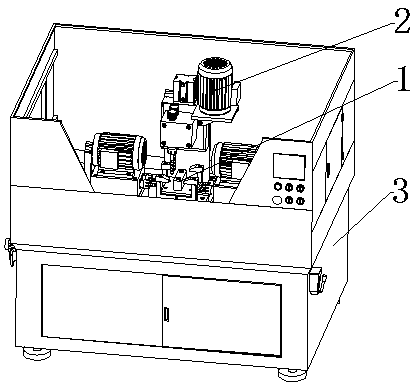
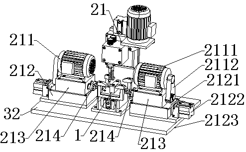
The invention discloses porous drill equipment which comprises a machine box, a control circuit, a drilling mechanism and a clamp mechanism. The clamp mechanism is arranged on a work platform of the machine box. The drilling mechanism at least comprises three drilling units, and the three drilling units are located on the two sides and the upper portion of the clamp mechanism correspondingly. Eachdrilling unit comprises a rotary assembly, a movement assembly, a drill bit mounting seat and drill bits. The drill bits are mounted on the drill bit mounting seats according to hole preset positions, and the drill bits face the direction of the clamp mechanism. The rotary assemblies are arranged on the drill bit mounting seats and used for driving the drill bits to rotate. The drill bit mountingseats are arranged on the movement assemblies, the movement assemblies are used for driving the drill bit mounting seats to move, and therefore the drill bits can move away from or towards the clampmechanism. The control circuit is arranged in the machine box and is electrically connected with the rotary assemblies and the movement assemblies. The porous drill equipment specially aims at the requirement of three-face perforating of a C-shaped structural component, and three-face perforating can be achieved through one-time locating.

Description

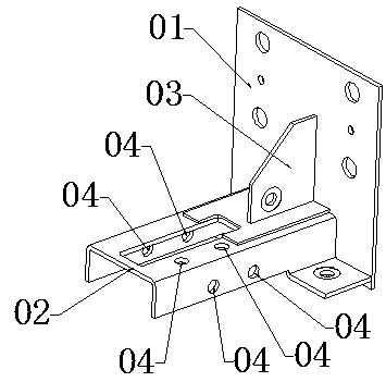
technical field [0001] The invention relates to the technical field of drilling equipment, in particular to a multi-hole drilling equipment. Background technique [0002] In the guiding system of the elevator, the guide shoe is a key component. The structure of a guide shoe accessory is as follows: figure 1 As shown, the guide shoe assembly includes a base plate part 01 , a C-shaped part 02 and a side wing part 03 . According to the matching requirements with other components, two through holes 04 need to be drilled on each side of the C-shaped part 02, and two through holes 04 should be drilled on the upper part of one side, that is, a total of six through holes need to be drilled 04, see the specific hole position figure 1 . When the drilling equipment of the prior art drills a plurality of holes, generally there are two kinds of cooperation modes. One is to re-clamp the workpiece after drilling a hole, and drill other holes with the drill bit. This method requires mu...

Claims


Application Information

Patent Timeline
Patent Type & Authority Applications(China)
IPC IPC(8): B23B39/16B23Q3/08
CPCB23B39/16B23Q3/062B23Q3/08
Inventor 黎铮铮邓立清彭沛雄易玉华
Owner 凌彩百川(新兴)科技有限公司
Learn More