Pipe dropping device for laser pipe cutter
A blanking device and pipe cutting machine technology, applied in laser welding equipment, welding equipment, metal processing equipment and other directions, can solve the problems of affecting the processing accuracy of steel pipes, inconvenient blanking, inapplicability, etc., to reduce labor intensity, blanking Convenience and increased stability
- Summary
- Abstract
- Description
- Claims
- Application Information
AI Technical Summary
Problems solved by technology
Method used
Image

Examples
Embodiment
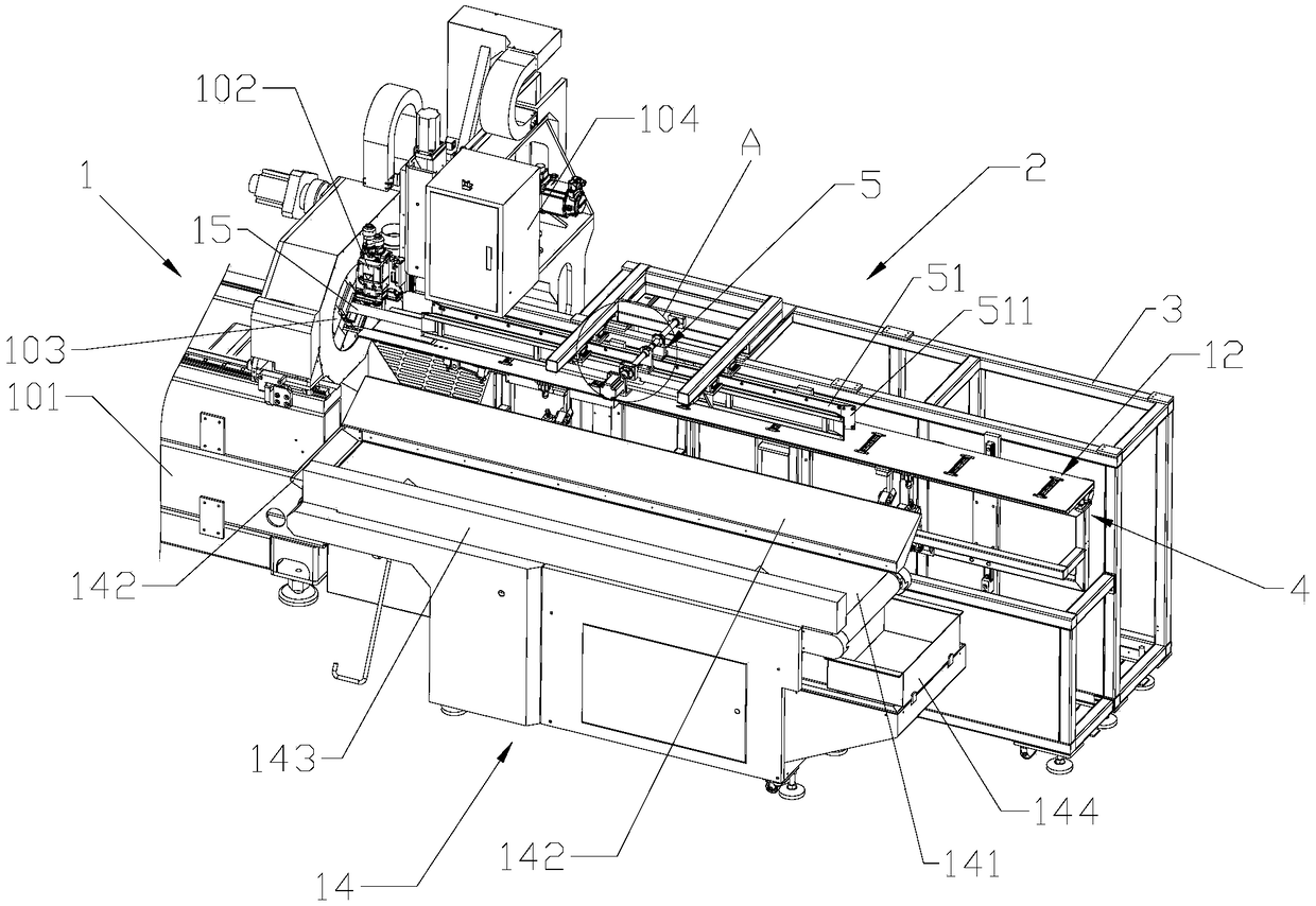
[0047] refer to figure 1 , this embodiment discloses a pipe blanking device for a laser pipe cutting machine, which is used in conjunction with a laser cutting machine 1, and includes a pipe support device 2 and a receiving and conveying assembly 14. One end of the material, the pipe support device 2 includes a mounting bracket 3 , a horizontal support assembly 4 and an anti-swing assembly 5 arranged on the mounting bracket 3 .
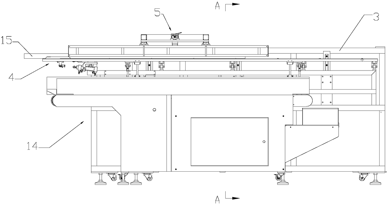
[0048] refer to image 3 as well as Figure 4 The mounting bracket 3 is provided with a lifting drive assembly 6 that drives the horizontal support assembly 4 to lift vertically. The horizontal support assembly 4 includes a support base plate 41 and a support platform 42. The support base plate 41 is movable in the vertical direction relative to the mounting bracket 3. At least one vertical guide rail 8 is fixedly arranged on the mounting bracket 3, at least one vertical slider 81 is fixedly arranged on the support base plate 41, and the vertical sl...
PUM
 Abstract
Description
Claims
Application Information