Thermal management system and control method for fuel cell vehicle

A thermal management system and fuel cell technology, applied in battery/fuel cell control devices, fuel cell heat exchange, fuel cells, etc., can solve problems such as failure to start, deterioration of battery discharge capacity, uneven heating of stacks, etc., to reduce Power consumption, improvement of energy utilization, and effect of reducing discharge load

A thermal management system and fuel cell technology, applied in battery/fuel cell control devices, fuel cell heat exchange, fuel cells, etc., can solve problems such as failure to start, deterioration of battery discharge capacity, uneven heating of stacks, etc., to reduce Power consumption, improvement of energy utilization, and effect of reducing discharge load

CN109291830BActive Publication Date: 2019-12-20JILIN UNIV

Image

  • Thermal management system and control method for fuel cell vehicle
  • Thermal management system and control method for fuel cell vehicle
  • Thermal management system and control method for fuel cell vehicle

Examples


Embodiment Construction

[0044] The present invention will be further described in detail below in conjunction with the accompanying drawings, so that those skilled in the art can implement it with reference to the description.

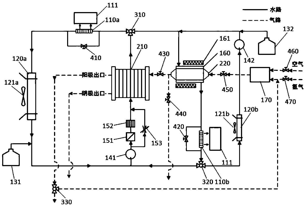
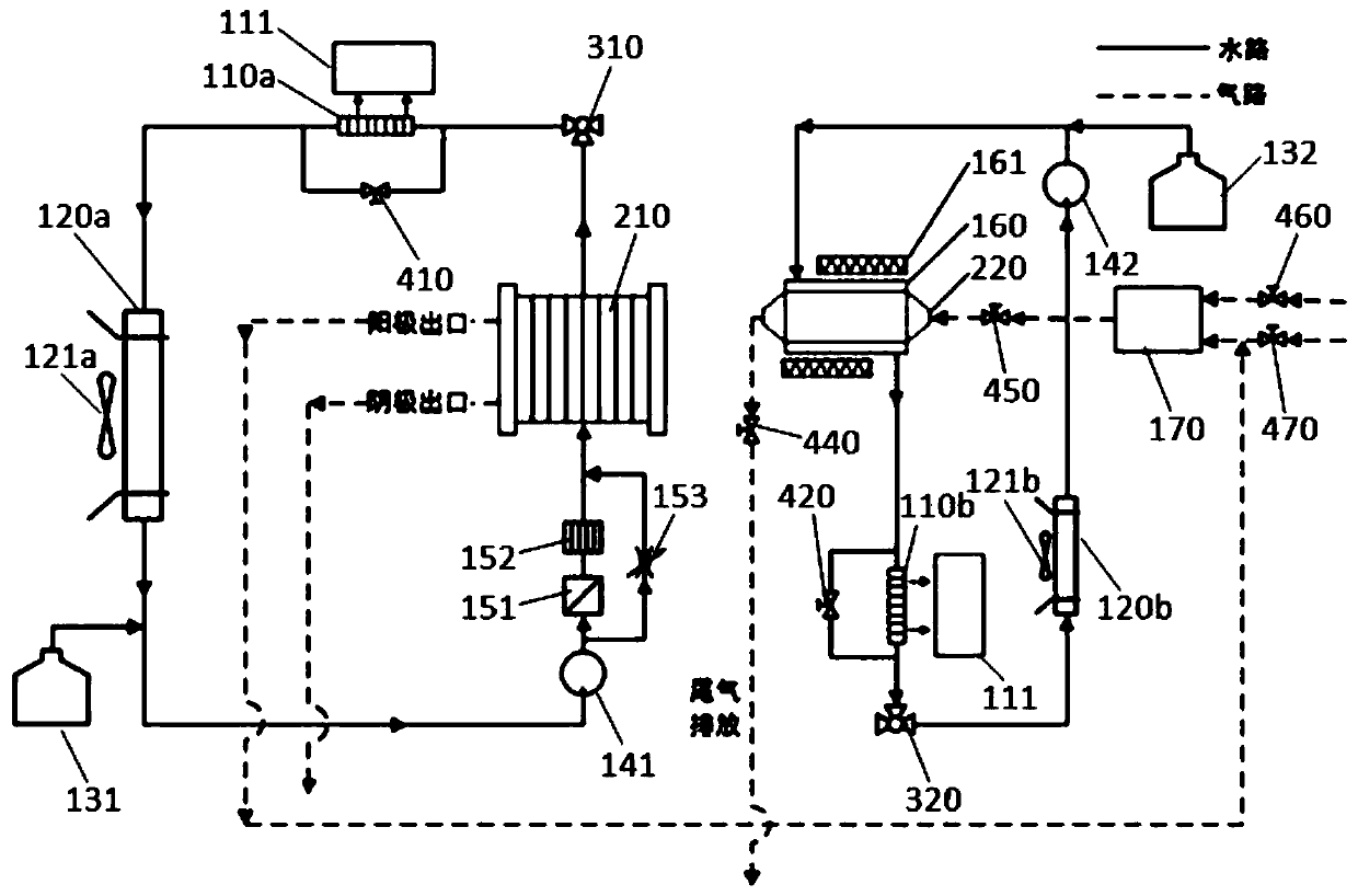
[0045] Such as figure 1 As shown, the present invention provides a fuel cell vehicle thermal management system, which mainly includes:

[0046] The sequentially connected hydrogen fuel cell stack 210, the first electronically controlled three-way valve 310, the first passenger compartment heat exchanger 110a, the first radiator 120a and the first variable frequency water pump 141 form a communication circuit, and the first passenger compartment is exchanged The heater 110a is provided with a first electromagnetic valve 410;

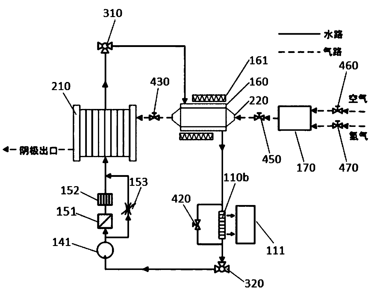
[0047] The sequentially connected hydrogen fuel cell stack 210, the first electronically controlled three-way valve 310, the heat exchanger 160, the second passenger compartment heat exchanger 110b, the second electronically controlled three-way valve 3...


PUM


Abstract

The invention discloses a thermal management system for a fuel cell vehicle, comprising a hydrogen fuel cell stack, a hydrogen catalytic combustion reactor, an electric heater, a frequency conversion fan, a water supply tank, a frequency conversion water pump, a deionization device, a particle filter, and a bypass valve , temperature sensor and controller. The invention discloses a control method for a thermal management system of a fuel cell vehicle.

Description

technical field [0001] The invention relates to the field of fuel cell vehicles, in particular to a fuel cell vehicle thermal management system and a control method thereof. Background technique [0002] A proton exchange membrane fuel cell is a device that directly converts chemical energy into electrical energy. Because of its high efficiency, zero emissions, low noise and low operating temperature, it is considered to be an ideal substitute for future vehicle power sources, and has attracted the attention of governments around the world. With the advancement of technology, some fuels are currently Battery cars have entered commercial operation. [0003] One of the problems faced by vehicle fuel cells is the start-up in low temperature environment. At present, the heating device of most fuel cell vehicle thermal management systems is electric heating, but in low temperature environment, if the power battery is used as the source of electric heating device , The power bat...

Claims


Application Information

Patent Timeline
20 Dec 2019
Publication
CN109291830B
IPC
B60L58/34; B60H1/22; H01M8/04014; H01M8/04029
CPC
H01M8/04022; H01M8/04029; B60H1/2203; Y02T90/40; Y02E60/50; H01M2008/1095; H01M8/04225; H01M8/04268
Inventors
闵海涛; 王博石