Gas well drainage and production process evaluation system integration and method

An evaluation system and evaluation method technology, applied in the field of gas well drainage and production process evaluation system integration, can solve problems such as insufficient utilization of test platforms, waste of costs, etc., and achieve the effects of saving device configuration costs, convenient operation, and reducing device space occupied

Inactive Publication Date: 2019-02-01
CHINA NAT OFFSHORE OIL CORP +1
View PDF11 Cites 2 Cited by
  • Summary
  • Abstract
  • Description
  • Claims
  • Application Information

AI Technical Summary

Problems solved by technology

[0005] In order to solve the problems in the prior art, the present invention provides a gas well drainage process evaluation system integration and method, which solves the need to develop a set of test platforms separately for the evaluation of the application effect of the gas well drainage process in the prior art, and the waste of cost And the problem of insufficient utilization of the test platform

Method used


Image

  • Gas well drainage and production process evaluation system integration and method
  • Gas well drainage and production process evaluation system integration and method
  • Gas well drainage and production process evaluation system integration and method

Examples


Embodiment 1

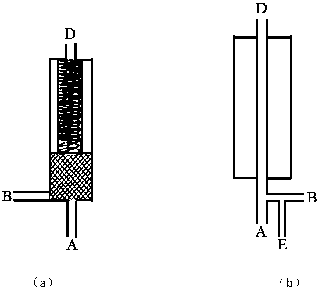
[0037] Example 1: Downhole cyclone separator gas-liquid separation efficiency method;

[0038] The separation efficiency of the downhole cyclone separator is calculated by experimentally measuring the gas output from the gas phase outlet after separation and the gas output from the liquid phase outlet of the separator. The calculation formula is as follows:

[0039]

[0040] Among them, η is the gas phase separation efficiency of the cyclone separator; Q g(d) Is the gas output after separation; Q g(l) It is the gas output of the liquid phase outlet of the separator.

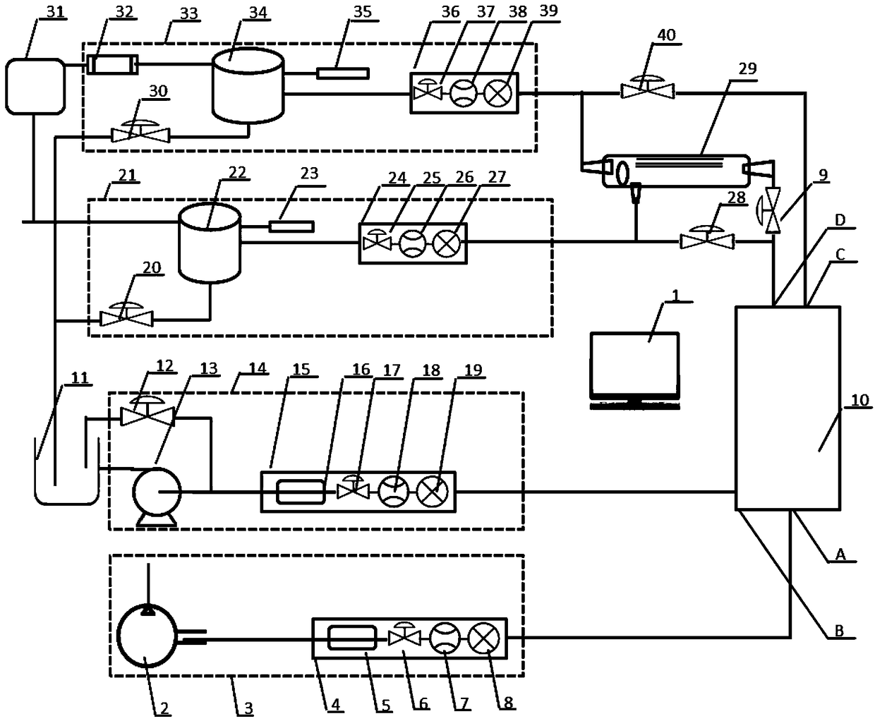
[0041] Experiment: Install a gas-liquid separator in the gas well drainage process evaluation device 10; close the valve 9. Start the plunger pump 13 in the liquid supply device 14. The plunger pump 13 pumps the liquid to the liquid regulator 15 for liquid temperature and pressure adjustment and delivery to the gas well drainage process evaluation device 10, and at the same time starts the gas supply device 3 The gas c...

Embodiment 2

[0043] Example 2: Critical liquid-carrying velocity method for gas wells;

[0044] The critical liquid-carrying velocity of gas wells is calculated by experimentally measuring the minimum gas production volume of continuous gas-carrying liquid under different temperature, pressure and different liquid accumulation conditions. The calculation formula is as follows:

[0045]

[0046] Where υ t Indicates the minimum critical liquid carrying speed; q c It is the minimum gas production volume of continuous liquid carrying in the gas well; T is the temperature; p is the pressure; A is the cross-sectional area of ​​the pipe string; z is the gas deviation factor under the conditions of p and T.

[0047] Experiment: Install the gas lift device of the drainage tool in the gas well drainage process evaluation device 10, start the plunger pump 13 in the liquid supply device 3, and the plunger pump 13 pumps the liquid to the liquid regulator 15 for liquid temperature and pressure adjustment , The...

Embodiment 3

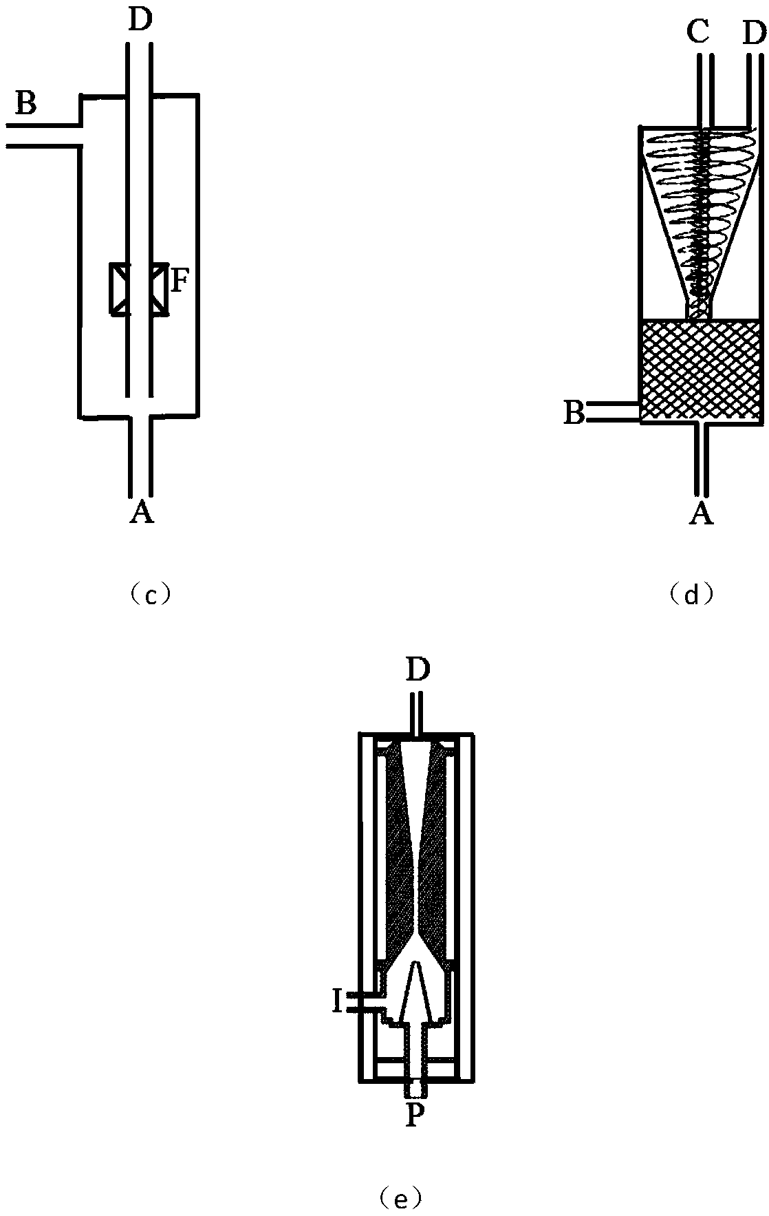
[0049] Embodiment 3: Liquid-gas jet pump pump efficiency method;

[0050] Calculated by experimentally measuring jet pump power fluid pressure, suction port pressure, discharge port pressure, power fluid flow and suction gas flow, the calculation formula is as follows:

[0051]

[0052] Among them, η represents the pumping efficiency of the liquid-gas jet pump; p 1 Represents power hydraulic pressure; p 2 Indicates the pressure of the sucked gas; p 3 Indicates discharge outlet pressure; Q 1 Indicates the flow of power fluid; Q 2 Indicates the flow of gas being sucked in.

[0053] Experiment: Install the drainage tool liquid-gas jet pump in the gas well drainage process evaluation device 10, start the plunger pump 13 in the liquid supply device 14, and the plunger pump 13 pumps the liquid to the liquid regulator 15 for liquid temperature , Pressure adjustment, after adjustment, the liquid enters the gas well drainage process evaluation device 10, and at the same time the gas compresso...


PUM


Abstract

The invention discloses gas well drainage and production process evaluation system integration and method. The gas well drainage and production process evaluation system integration is a set of systemintegrated by five gas well drainage and production process evaluation systems, and comprises a gas supplying device, a liquid supplying device, a drainage and production process evaluation device, agas treating device and a liquid treating device; and the gas well drainage and production process evaluation method is constituted by four gas well drainage and production process evaluation methodsof the cyclone separator gas-liquid separation efficiency, the gas well critical liquid carrying gas volume, the liquid-gas jet pump efficiency and the gas-liquid jet pump efficiency. The investmentcost can be lowered, the success rate of a drainage and production process device applied to a site is increased, and the important effect on gas well stable production is achieved.

Description

Technical field [0001] The present invention relates to the field of petroleum development, in particular to the integration and method of gas well drainage process evaluation system. Background technique [0002] In the process of oil and gas field development, the water content of gas wells will continue to rise, causing fluid accumulation in the wellbore of the gas well or even water flooding and stopping. The increasing water production of gas wells poses a serious threat to the production of natural gas. The accumulation of liquid at the bottom of the well will cause a decrease in gas production. Reducing or even stopping production affects the efficient development of gas fields; in some oil wells with high gas-liquid ratio, the higher gas-liquid ratio affects the normal operation of mechanical production equipment. The current solution is mainly to use some drainage and gas production processes to continue the production of gas wells. These drainage and gas production proc...

Claims


Application Information

Patent Timeline
IPC IPC(8): E21B43/00E21B47/00
CPCE21B43/12E21B47/00
Inventor 赵景辉杨万有郑春峰李昂任维娜谢双喜程心平沈琼苏作飞尹莎莎
Owner CHINA NAT OFFSHORE OIL CORP
Why Eureka
Try Eureka