Flow scattering integration device for water conservation power generation blades

A technology of integrated devices and power generation blades, which is applied in the directions of hydropower generation, machines/engines, and reaction engines, etc. It can solve the problems of large water flow impact, low utilization rate of water energy into electrical energy, and large resistance.

Inactive Publication Date: 2019-02-01
陈俊敏
View PDF0 Cites 0 Cited by
  • Summary
  • Abstract
  • Description
  • Claims
  • Application Information

AI Technical Summary

Problems solved by technology

[0003] The water flow on the surface of the mountain falls under the influence of gravity and hits the power generation mixed flow runner blades. Since the power generation mixed flow runner blades need to be connected with the external generator set through the large shaft, and the connection between the power generation mixed flow runner blades and the large shaft The end surface of the blade is flat, and the impact of the water flow can only be received unilaterally through the three-dimensional twisted surface body in the middle of the blade of the power generation mixed flow runner, so that the impact of the water flow in the middle is large (large resistance), causing the water flow to disperse to the upper and lower surfaces of the blade of the power generation mixed flow runner , the three-dimensional distorted curved surface body cannot receive the hydraulic impact, and the blades of the mixed-flow runner for power generation cannot receive the impact force of the falling water flow well, so that the utilization rate of water energy into electrical energy is not high

Method used


Image

  • Flow scattering integration device for water conservation power generation blades
  • Flow scattering integration device for water conservation power generation blades
  • Flow scattering integration device for water conservation power generation blades

Examples


Embodiment

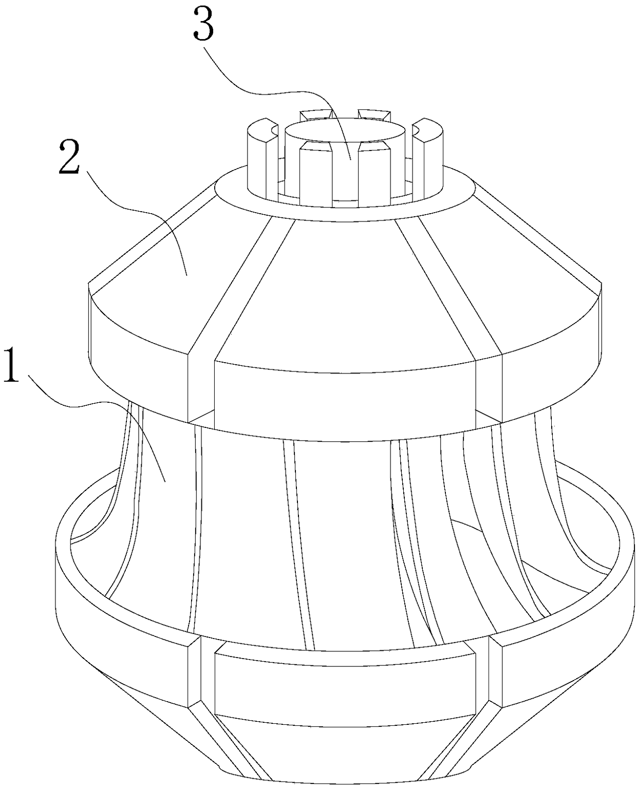
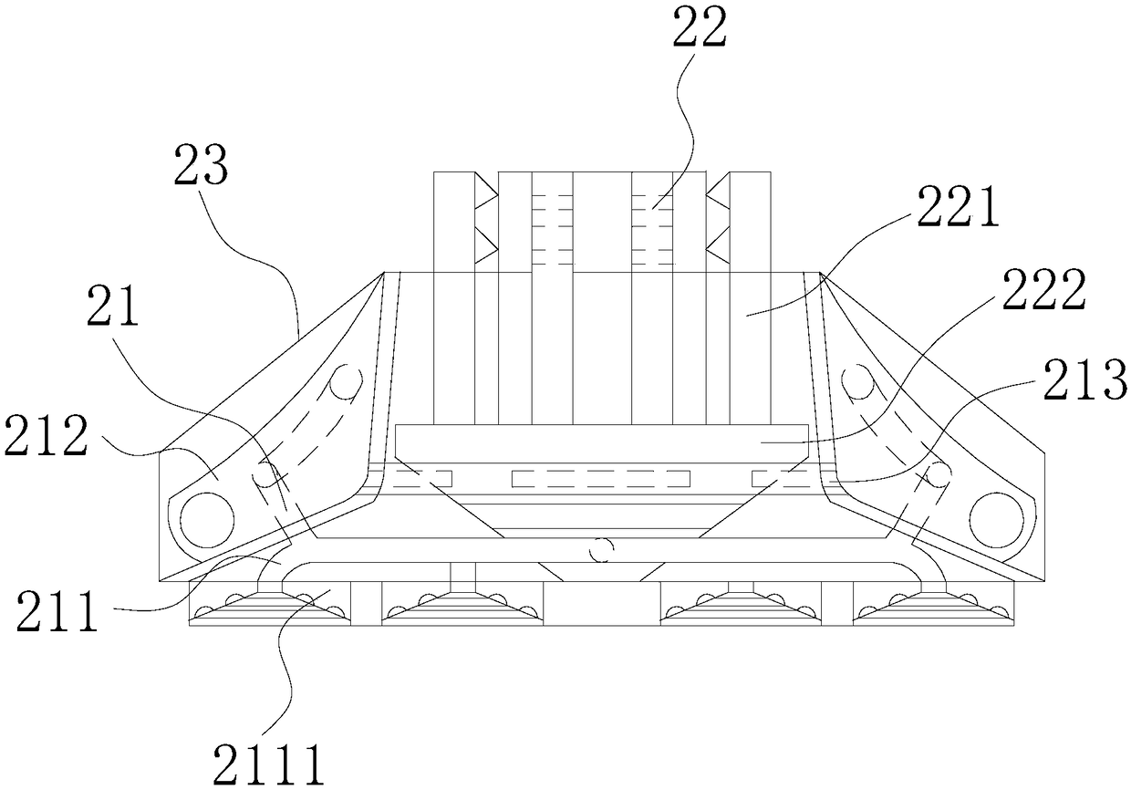
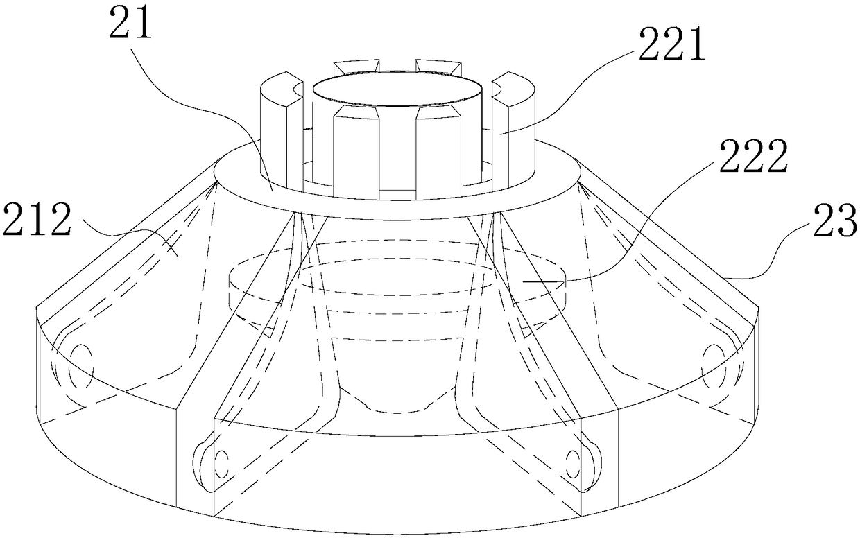
[0020] Such as Figure 1-Figure 6 As shown, the present invention provides a diffuse flow integration device for hydropower generation blades, the structure of which includes a blade 1, a diffuse flow integration device 2, and a large external shaft 3, and the blade 1 is vertically embedded and installed under the diffuse flow integration device 2 position, the external large shaft 3 is vertically installed on the upper end of the diffuse flow integration device 2, the external large shaft 3 is mechanically connected to the blade 1 through the diffuse flow integration device 2, and the diffuse flow integration device 2 includes an expansion mechanism 21, Push-off mechanism 22, casing 23, described expansion mechanism 21 is horizontally installed in the middle position inside casing 23, and described push-off mechanism 22 is vertically installed in the inside of casing 23, and described expansion mechanism 21 and push-off mechanism 22 are carried out mechanically by water flow. ...


PUM


Abstract

The invention discloses a flow scattering integration device for water conservation power generation blades. The flow scattering integration device structurally comprises the blades, a flow scatteringintegration device body and an outer connection large shaft. After water flow enters conical pipes through water flow impacts, the water flow is guided into water material pipes, one part of water flow enters folding pipes in swinging circling blades, the swinging circling blades pull a tenacity extending plate to be outwards expanded along an outer embedded ring plate, the six swinging circlingblades are knocked out, the tenacity extending plate is used for pulling the swinging circling blades to be stably located at the same horizontal position, the swinging circling blades are used for receiving scattered water flow impacts, and the water power is increased; meanwhile, water flow enters a water injection conical disc through an annular pipe, through water flow in the water injection conical disc, a linkage plate drives foot rods to rotate, extrusion convex plates are used for constantly movably jacking the foot rods, the foot rods conduct cutting around the outer surface of the large shaft, runner blades can integrally receive the water flow impacts through the swinging circling blades, the utilization rate of electric energy converted through water flow is increased, and it can be guaranteed that the outer connection large shaft does not bear resistance.

Description

technical field [0001] The invention relates to the field of hydropower generation, in particular to a diffuse flow integration device for blades of hydropower generation. Background technique [0002] Hydropower generation blades are runner blades that receive water from the outside of the mountain through a three-dimensional twisted surface and convert water energy into mechanical energy. However, the existing horizontal hydropower generation mixed-flow blades are installed inside the mountain, and the water flow vertically collides with the power generation runner blades. There are following problems: [0003] The water flow on the surface of the mountain falls under the influence of gravity and hits the power generation mixed flow runner blades. Since the power generation mixed flow runner blades need to be connected with the external generator set through the large shaft, and the connection between the power generation mixed flow runner blades and the large shaft The e...

Claims


Application Information

Patent Timeline
Patent Type & Authority Applications(China)
IPC IPC(8): F03B3/12
CPCF03B3/125Y02E10/20
Inventor 陈俊敏
Owner 陈俊敏
Why Eureka
Try Eureka