Bearing with blade type retainer

A cage and blade type technology, applied in the field of bearings with blade type cage, can solve the problems of poor bearing lubrication and heat dissipation performance, and achieve the effect of good oil guiding effect, speeding up the flow rate and prolonging the service life.

Inactive Publication Date: 2019-02-01
BEIJING INSTITUTE OF TECHNOLOGYGY
View PDF10 Cites 2 Cited by
  • Summary
  • Abstract
  • Description
  • Claims
  • Application Information

AI Technical Summary

Problems solved by technology

[0005] The purpose of the present invention is to solve the problem of poor lubricating and heat dissipation performance of existing bearings, and provide a bearing with blade type cage

Method used


Image

  • Bearing with blade type retainer
  • Bearing with blade type retainer
  • Bearing with blade type retainer

Examples


Embodiment 1

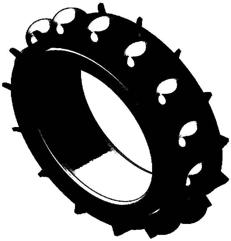
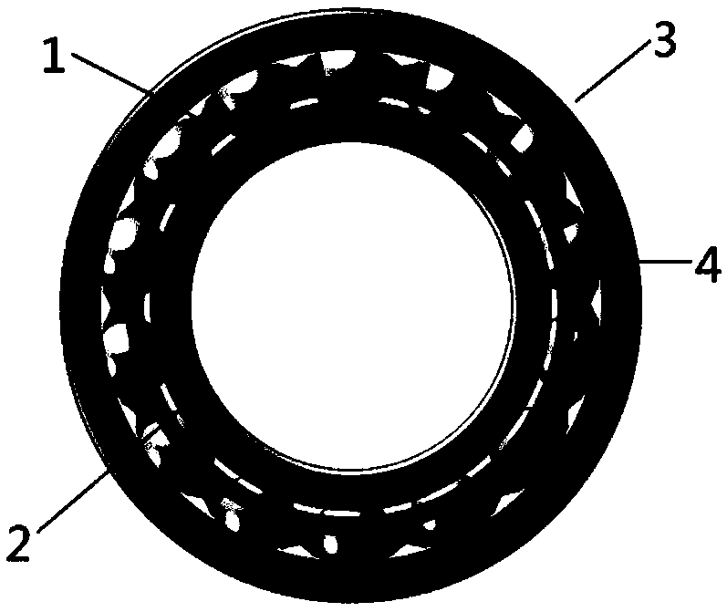
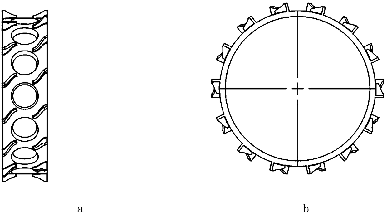
[0026] A bearing with a vane cage, such as figure 1 , figure 2 , image 3 As shown, it includes: cage 1, bearing inner ring 2, bearing outer ring 3 and roller 4. Cage 1, bearing inner ring 2, bearing outer ring 3 and roller 4 are assembled into a bearing;

[0027] The outer surface of the cage 1 has a blade-type boss, which has a certain angle with the bearing axis, and the blade-type boss can play the role of forced oil guide, that is, fluids such as lubricating oil and air are introduced into the bearing In the ring, or between the roller and the cage;

[0028] The blade-type bosses are arranged on the outside of the cage in two rows, arranged in a reverse symmetrical circle, so as to ensure that no matter how the rotation direction of the bearing changes, the fluid can always be forced to enter the inside of the bearing;

[0029] The end of the boss close to the roller needs to keep a gap with the roller to prevent the boss from affecting the movement of the roller and...


PUM


Abstract

The invention relates to a bearing with a blade-type retainer, and belongs to the field of bearings. With the adoption of the retainer, fluids such as lubricating oil splashed to the side surface of the bearing can be guided into the bearing and are guided out of the bearing after fully flowing between an inner ring and an outer ring, so that the lubricating conditions in the bearing are improvedgreatly and the service life of the bearing is prolonged. Casting blades on the retainer does not affect the radial or axial bearing capacity, rotation accuracy and transmission power of the inner ring and the outer ring of the bearing. The blades are cast between rolling bodies, so that space resources of the retainer is used fully, the rotation and revolution of the rolling bodies are not impeded, and the machining is easy. The bearing can be applied to high-speed bearings such as an aeroengine bearing, a turbomachinery bearing and a power transmission bearing; and when the higher the DN value of the bearing is, the more obvious the lubricating effect of the bearing is, and the more significant the circulation acceleration effect on the fluids such as the lubricating oil and air is.

Description

technical field [0001] The invention relates to a bearing with a vane type cage, which belongs to the field of bearings. Background technique [0002] The cage (also known as the bearing cage) refers to the bearing part that partially wraps all or part of the rolling elements and moves accordingly. Its function is to separate the rolling elements in the bearing at equal distances and guide the rolling elements on the correct track. movement, improving the internal load distribution and lubrication characteristics of the bearing. [0003] There is no redundant fluid guiding design on the traditional bearing cage, the structure is simple, the space utilization rate between the inner and outer rings of the bearing is low, and the lubrication effect is not obvious. For example, Chinese patent CN202500902U: a cage for cylindrical roller bearings, the designed cage is provided with oil grooves on the pillars connecting the retaining rings on both sides, so that the bearing roller...

Claims


Application Information

Patent Timeline
Patent Type & Authority Applications(China)
IPC IPC(8): F16C19/16F16C33/38F16C33/66F16C37/00
Inventor 吴维刘印胡纪滨苑士华
Owner BEIJING INSTITUTE OF TECHNOLOGYGY
Why Eureka
Try Eureka