Flow channel switching micro-valve structure for micro-fluidic chip and switching control method thereof

A microfluidic chip, flow channel switching technology, applied in chemical instruments and methods, valve devices, laboratory utensils and other directions, can solve the problems of high production cost, high production difficulty, complex structure design, etc. The switching action is stable and accurate, and the operation is simple and convenient.

Active Publication Date: 2019-02-01
CHANGZHOU VOCATIONAL INST OF ENG
View PDF14 Cites 7 Cited by
  • Summary
  • Abstract
  • Description
  • Claims
  • Application Information

AI Technical Summary

Problems solved by technology

[0008] The purpose of the present invention is to overcome the disadvantages of the existing microfluidic chip microvalve such as complex structure design, high manufacturing difficulty, and high manufacturing cost, and provide a microfluidic chip channel switching microvalve structure and a switching control method thereof. The technical scheme provides a new type of mechanical microvalve structure, which uses the air passage to blow the switching ball valve in the valve cavity to realize the rapid switching of the flow channel in the microfluidic chip. The structure is simple, the processing is convenient, and the production cost is low. , and the switching action of the micro valve is stable and reliable, and the operation is simple and convenient

Method used


Image

  • Flow channel switching micro-valve structure for micro-fluidic chip and switching control method thereof
  • Flow channel switching micro-valve structure for micro-fluidic chip and switching control method thereof

Examples


Embodiment

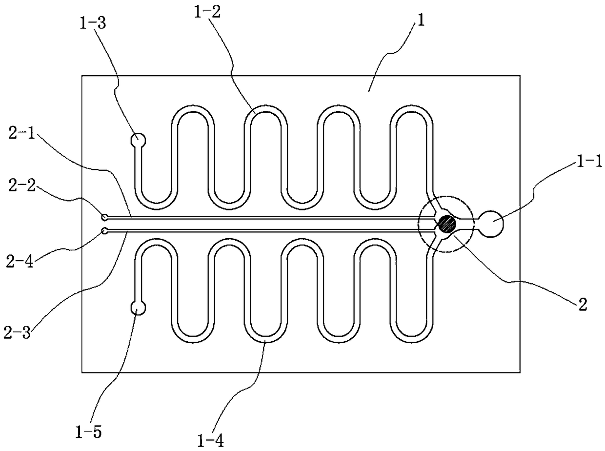
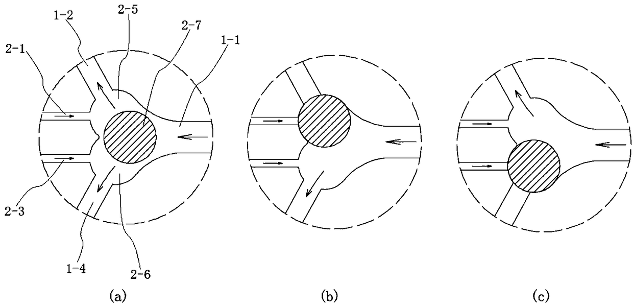
[0034] combine figure 1 and figure 2As shown, a microfluidic chip channel switching microvalve structure in this embodiment includes a microfluidic chip 1 and a switching microvalve 2 disposed in the microfluidic chip 1, and the microfluidic chip 1 has a first channel 1-2 and the second flow channel 1-4, the specific shapes of the first flow channel 1-2 and the second flow channel 1-4 are designed according to the working requirements of the microfluidic chip 1, the first flow channel 1-2 and the The second flow channel 1-4 is connected to the liquid inlet 1-1 on the microfluidic chip 1 through the switching microvalve 2, and the end of the first flow channel 1-2 is provided with a first liquid outlet 1-3, and the second flow channel The end of 1-4 is provided with a second liquid outlet 1-5, and the liquid enters through the liquid inlet 1-1, and the switching microvalve 2 is used to select one of the first flow channel 1-2 and the second flow channel 1-4 In the flow chann...


PUM


Abstract

The invention discloses a flow channel switching micro-valve structure for a micro-fluidic chip and a switching control method thereof, and belongs to the field of microfluidics. The flow channel switching micro-valve structure for the micro-fluidic chip comprises the micro-fluidic chip and a switching micro-valve arranged in the micro-fluidic chip, wherein the switching micro-valve comprises a first valve cavity, a second valve cavity, a middle switching valve cavity and a switching ball valve, the switching ball valve is arranged in the middle switching valve cavity, and can enter the firstvalve cavity to block a first flow channel or enter the second valve cavity to block a second flow channel, the first valve cavity communicates with a first air inlet channel capable of blowing out the switching ball valve from the first valve cavity, and the second valve cavity communicates with a second air inlet channel capable of blowing out the switching ball valve from the second valve cavity. According to the provided novel mechanical type micro-valve structure, an air channel is used for blowing the switching ball valve arranged in the valve cavity to achieve rapid switching of the flow channels in the micro-fluidic chip, the structure is simple, machining and manufacturing are convenient, the manufacturing cost is low, moreover, the micro-valve switching action is stable and reliable, and the operation is simple and convenient.

Description

technical field [0001] The invention relates to the field of microfluidic chips, and more specifically relates to a microvalve structure for switching channels of a microfluidic chip and a switching control method thereof. Background technique [0002] Microfluidics is a new type of tool that integrates the basic operation units such as sample preparation, reaction, separation, and detection in the process of biological, chemical, and medical analysis into a micron-scale chip, and automatically completes the entire analysis process. . Microfluidic chips process functional units such as micropipes, microvalves, micropumps, microreactors, electrodes, etc. Various operations on samples at the micron scale. Among them, the microvalve is mainly responsible for supervising the work of each flow path in the chip, regulating the pressure and movement state of the fluid in the chip, similar to the "traffic lights" in the urban traffic system, and is an important unit in the microfl...

Claims


Application Information

Patent Timeline
Patent Type & Authority Applications(China)
IPC IPC(8): F16K99/00B01L3/00
CPCF16K99/0005F16K99/0055B01L3/502738B01L2200/10B01L2200/027B01L2300/049Y02A50/30
Inventor 王晓东乔奇伟沙俊刘承先李树白薛叙明周海浪孙福
Owner CHANGZHOU VOCATIONAL INST OF ENG
Why Eureka
Try Eureka