An Electromagnetic Brake System for Fast Compressors

An electromagnetic braking and compressor technology, which is used in engine testing, machine/structural component testing, and instrumentation. , Reduce braking noise, accurate and reliable experimental data

Active Publication Date: 2020-02-07
TIANJIN UNIV
View PDF8 Cites 0 Cited by
  • Summary
  • Abstract
  • Description
  • Claims
  • Application Information

AI Technical Summary

Problems solved by technology

But this approach has some drawbacks
For example, hydraulic braking often causes the phenomenon of piston rebound, which changes the thermodynamic state in the cylinder, affects the spontaneous combustion delay period of the fuel, the combustion phase in the cylinder, and other processes, thus causing deviations in the experimental results

Method used


Image

  • An Electromagnetic Brake System for Fast Compressors
  • An Electromagnetic Brake System for Fast Compressors
  • An Electromagnetic Brake System for Fast Compressors

Examples


Embodiment Construction

[0016] The technical method of the present invention will be further described in detail below in conjunction with the accompanying drawings and specific embodiments, but the present invention is not limited to this specific embodiment, and this description is not intended to limit the present invention.

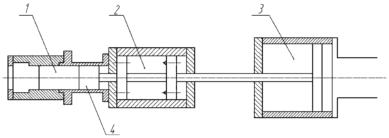
[0017] Such as figure 1 As shown, it is a structural schematic diagram of a fast compressor adopting the electromagnetic braking system of the present invention, including a combustion device 1 , an electromagnetic braking system 2 , a driving device 3 and a piston 4 .

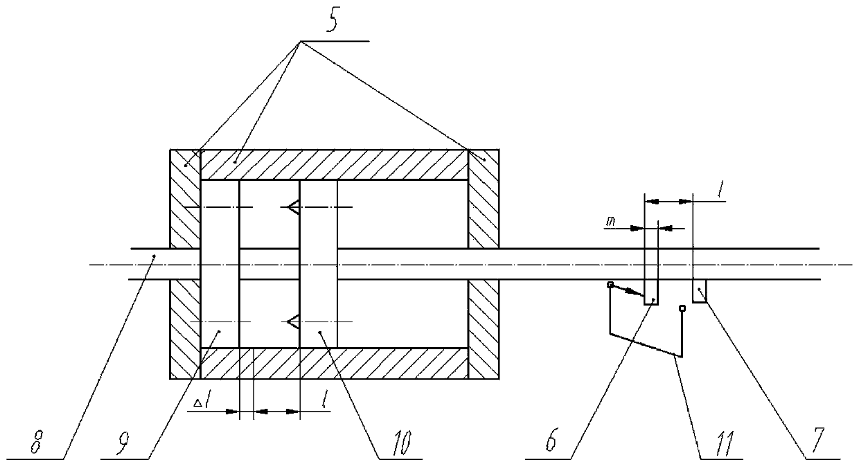
[0018] figure 2 It is a structural schematic diagram of the electromagnetic braking system of the present invention. It consists of a brake cylinder 5 made of magnetic isolation material, a push rod 8 passing through the brake cylinder, an electromagnetic brake ring 9 fixed on the brake cylinder 5 and an electromagnetic brake piston 10 fixed on the push rod 8 And two light-shielding plates 6,7 and the pho...


PUM


Abstract

The invention relates to an electromagnetic braking system for a rapid compressor. The electromagnetic braking system comprises a central control unit, a braking cylinder made of a magnetic separationmaterial, a pushing rod penetrating through the braking cylinder, an electromagnetic braking circular ring fixed to the braking cylinder, an electromagnetic braking piston fixed to the pushing rod, afirst light shading plate, a second shading plate, a photoelectric sensor and an electromagnetic braking control circuit, wherein the first light shading plate and the second shading plate are fixedto the pushing rod, and the photoelectric sensor is fixed nearby the pushing rod. Circumferentially-wound electromagnetic coils are embedded on the electromagnetic braking circular ring and the electromagnetic braking piston correspondingly; the two light shading plates are fixed to the corresponding positions on the pushing rod when baking needs to be started and needs to be completed, the distance between the two light shading plates is equal to the braking distance l, and the photoelectric sensor is arranged at the first light shading plate when braking is started; and the photoelectric sensor sends detection signals on the two light shading plates into the central control unit.

Description

technical field [0001] The invention is a control method based on a fast compressor electromagnetic braking system, which relates to the technical field of engines, in particular to a fast compressor braking system for engine simulation. Background technique [0002] Fast Compressor is a basic experimental platform for simulating engine compression and combustion process. It uses external force to carry out the compression stroke, quickly moves the piston to the top dead center, compresses the gas in the cylinder, and then uses the brake system to stop the piston, so that the gas in the cylinder can be burned at high temperature and high pressure, simulating the single combustion process of the engine. Through the research on the combustion process of the fast compressor, the combustion situation in the cylinder when the engine runs to the top dead center can be obtained indirectly. Compared with the engine, the structure of the fast compressor is simple, and the complex in...

Claims


Application Information

Patent Timeline
Patent Type & Authority Patents(China)
IPC IPC(8): G01M15/00G01M15/02
CPCG01M15/00G01M15/02
Inventor 潘家营王磊卫海桥舒歌群刘昌文马国斌
Owner TIANJIN UNIV
Why Eureka
Try Eureka