
Ferromagnetic resonance probe

A ferromagnetic resonance and planar waveguide technology, applied in magnetic resonance measurement, nuclear magnetic resonance analysis, etc., can solve problems such as the tilt of the sample to be tested

Active Publication Date: 2019-02-01
CETHIK GRP +1
View PDF4 Cites 0 Cited by
  • Summary
  • Abstract
  • Description
  • Claims
  • Application Information

AI Technical Summary

Problems solved by technology

[0007] The main purpose of the present invention is to provide a ferromagnetic resonance probe to solve the problem that the sample to be tested is inclined to the planar waveguide in the detection process of the ferromagnetic resonance probe in the prior art

Method used


Image

  • Ferromagnetic resonance probe
  • Ferromagnetic resonance probe
  • Ferromagnetic resonance probe

Examples


Embodiment Construction

[0035] It should be noted that, in the case of no conflict, the embodiments in the present application and the features in the embodiments can be combined with each other. The present invention will be described in detail below with reference to the accompanying drawings and examples.

[0036] The present invention provides a ferromagnetic resonance probe, please refer to Figure 4 to Figure 6 , the ferromagnetic resonance probe includes a planar waveguide 10, the ferromagnetic resonance probe also includes: a base 20, the planar waveguide 10 is arranged on the base 20; a ballast assembly 30, the ballast assembly 30 is arranged on the base 20, and the ballast assembly 30 has a function On the carrying platform 31 carrying the sample 40 to be tested, the carrying platform 31 and the planar waveguide 10 are relatively movable, so as to press the sample 40 to be tested on the planar waveguide 10 .

[0037] The ferromagnetic resonance probe of the present invention realizes the f...


PUM


Abstract

The invention provides a ferromagnetic resonance probe. The ferromagnetic resonance probe comprises a planar waveguide and further comprises a base and a ballasting assembly; the planar waveguide is arranged on the base; the ballasting assembly is arranged on the base and provided with a bearing platform used for bearing a to-be-detected sample; and the bearing platform and the planar waveguide are arranged oppositely and movably so as to press the to-be-detected sample on the planar waveguide. According to the ferromagnetic resonance probe, the problem that as for a ferromagnetic resonance probe in the prior art, the situation that the to-be-detected sample is inclined to the planar waveguide is difficult to avoid in the detection process is solved; and a high-thermal-conductivity channelis established between the to-be-detected sample and the base, and fast and accurate control over the sample temperature is achieved.

Description

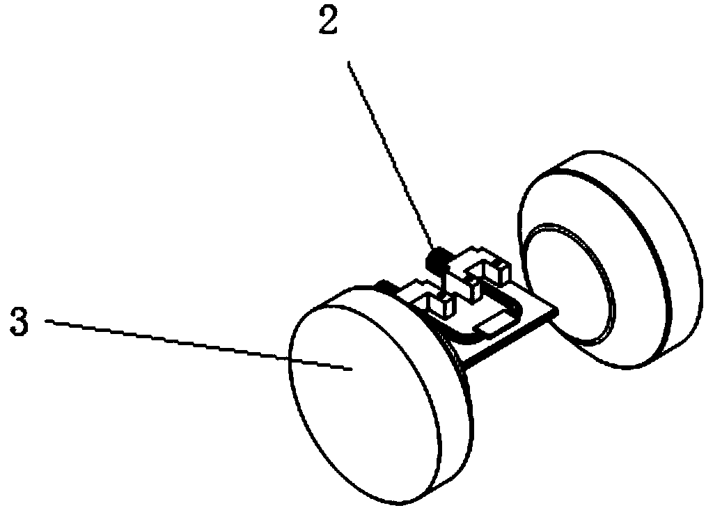
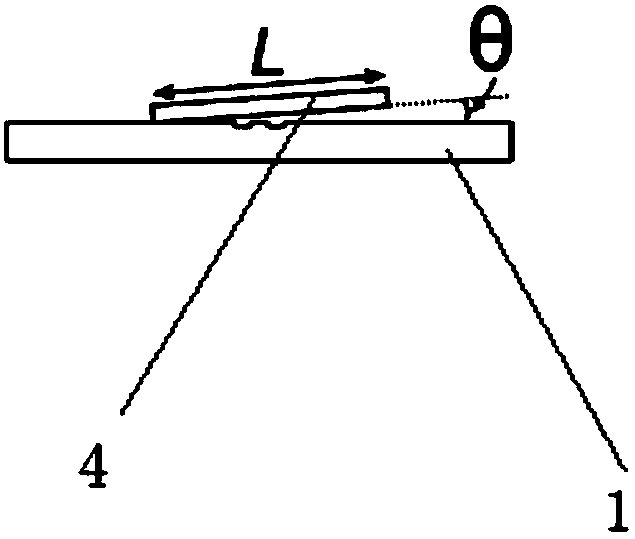
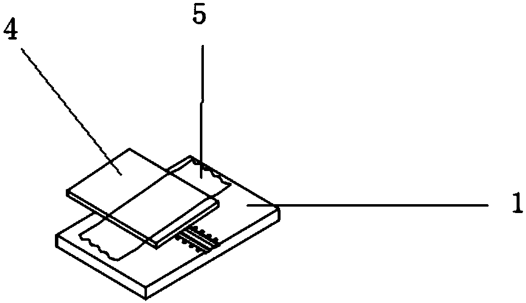
technical field [0001] The invention relates to the field of ferromagnetic resonance, in particular to a ferromagnetic resonance probe. Background technique [0002] The typical design schematic diagram of broadband ferromagnetic resonance under the existing parallel magnetic field is as follows: Figure 1 to Figure 3 shown. The basic components are back ground plane waveguide 1, high frequency connector 2 and electromagnet 3. The backside ground plane waveguide generates an RF field to drive and maintain the small-angle precession of the sample 4 magnetic moment. Since ferromagnetic resonance requires in principle that the magnetic field generated by microwaves must be perpendicular to the external magnetic field, the waveguide below sample 4 must be parallel to the external magnetic field; an electromagnet usually has a magnetic pole gap of several inches, and in order to achieve a higher magnetic field, further reduction is required. The gap is small, so the U-shaped pl...

Claims


Application Information

Patent Timeline
IPC IPC(8): G01R33/34G01N24/08
CPCG01N24/08G01R33/34G01R33/20
Inventor 何世坤
Owner CETHIK GRP
Learn More