A method, device and system for testing three-phase synchronization accuracy of a distribution line fault indicator
A fault indicator and three-phase synchronization technology, which is applied to measuring devices, instruments, and measuring electrical variables, etc., can solve problems such as the inability to correctly judge the time error of three-phase synchronization, and achieve effective and reliable judgment results and low test costs.
- Summary
- Abstract
- Description
- Claims
- Application Information
AI Technical Summary
Problems solved by technology
Method used
Image
Examples
Embodiment 1
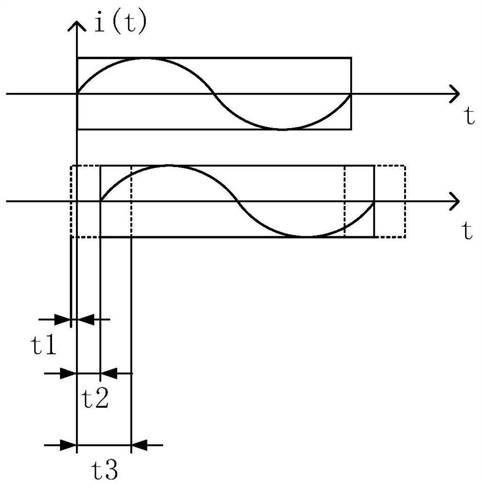
[0054] refer to image 3 As shown, a method for testing the three-phase synchronization accuracy of a distribution line fault indicator in this embodiment includes:
[0055] Obtain three sets of wave recording data corresponding to the sampling time, collected by the three-phase acquisition unit of the fault indicator in response to the test current waveform on the same line;
[0056] Taking any acquisition unit as a reference acquisition unit, and other acquisition units as comparison acquisition units, based on the set data window width, selecting continuously sampled wave recording data from the wave recording data corresponding to the reference acquisition unit, to obtain a reference wave recording data sequence;
[0057] Based on the previously set data window width, using the sliding window, within the set sliding range, each slide selects the continuously sampled wave recording data from the wave recording data corresponding to the control acquisition unit to obtain mul...
Embodiment 2
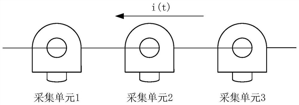
[0071] Based on the test method of embodiment 1, such as figure 1 As shown, the three-phase acquisition unit of the fault indicator to be tested is connected to the same phase line of the test bench, and then the test current waveform is passed to the primary side of the test bench.
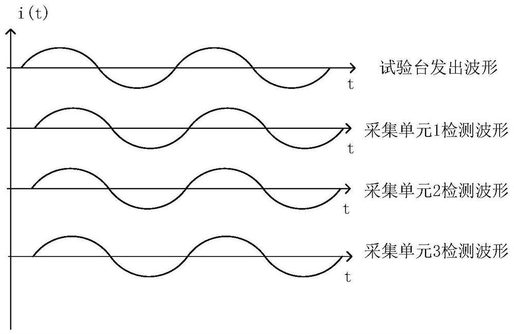
[0072] The three-phase acquisition unit of the fault indicator responds to the test current waveform respectively, and the collected current waveform can be obtained from the collection unit of the fault indicator. Refer to figure 2 , the acquisition waveforms of the three acquisition units inevitably have time synchronization errors due to various practical factors.
[0073] The three-phase acquisition unit of the fault indicator is defined as acquisition unit 1 / 2 / 3. In this embodiment, after acquiring the wave recording data of the three-phase acquisition unit, the acquisition unit 1-bit reference acquisition unit is selected, that is, the reference phase, and a fixed window is used to start f...
Embodiment 3
[0083] Based on the same inventive concept as Embodiments 1 and 2, this embodiment is a three-phase synchronization accuracy test device for a distribution line fault indicator, including: a wave recording data acquisition module, used to obtain the response of the three-phase acquisition unit of the fault indicator The three sets of wave recording data corresponding to the sampling time are collected from the test current waveform on the same line;
[0084] The reference wave recording data sequence selection module is used to select continuously sampled wave recording data from the wave recording data corresponding to the preset reference acquisition unit based on the set data window width to obtain the reference wave recording data sequence;
[0085] The relevant wave recording data sequence selection module is used to use the sliding window based on the previously set data window width, within the set sliding range, each time sliding from the wave recording data correspondi...
PUM
 Abstract
Description
Claims
Application Information
 - R&D
- Intellectual Property
- Life Sciences
- Materials
- Tech Scout
- Unparalleled Data Quality
- Higher Quality Content
- 60% Fewer Hallucinations
Browse by: Latest US Patents, China's latest patents, Technical Efficacy Thesaurus, Application Domain, Technology Topic, Popular Technical Reports.
© 2025 PatSnap. All rights reserved.Legal|Privacy policy|Modern Slavery Act Transparency Statement|Sitemap|About US| Contact US: help@patsnap.com


