Switched reluctance motor and controller for trailer braking and acceleration system

A technology of switched reluctance motor and acceleration system, applied in the direction of AC motor control, control system, electrical components, etc., can solve the problems of non-recovery of trailer braking energy, damage to small passenger cars, and separation of small passenger cars, etc. High starting torque and good speed regulation performance

Pending Publication Date: 2019-02-01
毛琦
View PDF0 Cites 0 Cited by
  • Summary
  • Abstract
  • Description
  • Claims
  • Application Information

AI Technical Summary

Problems solved by technology

[0002] Almost most small passenger cars in foreign countries will tow RVs or trailers carrying goods. This can greatly improve the loading capacity of small passenger cars and meet the requirements of car owners. However, there are strict requirements for small passenger car trailers in China. Because the scheme of increasing the loading capacity of the trailer vehicle has the following problems: 1. When the vehicle accelerates rapidly, especially when accelerating rapidly uphill, due to the sudden increase of the traction force and acting on the connection point between the minibus and the trailer, In addition, most of the small passenger cars today are load-bearing bodies, which can easily cause damage to the small passenger car, damage the connection points, cause the trailer to be separated from the small passenger car, and cause accidents
2. When the vehicle brakes suddenly, especially when braking downhill, due to the speed inertia of the trailer, a huge extrusion force acts on the connection point between the minibus and the trailer and on the minibus. It is a load-bearing body, which is very easy to cause damage to the small passenger car
3. Today, the braking energy recovery of small passenger cars is becoming more and more popular, but the braking energy of trailers cannot be recovered

Method used


Image

  • Switched reluctance motor and controller for trailer braking and acceleration system
  • Switched reluctance motor and controller for trailer braking and acceleration system

Examples


Embodiment 1

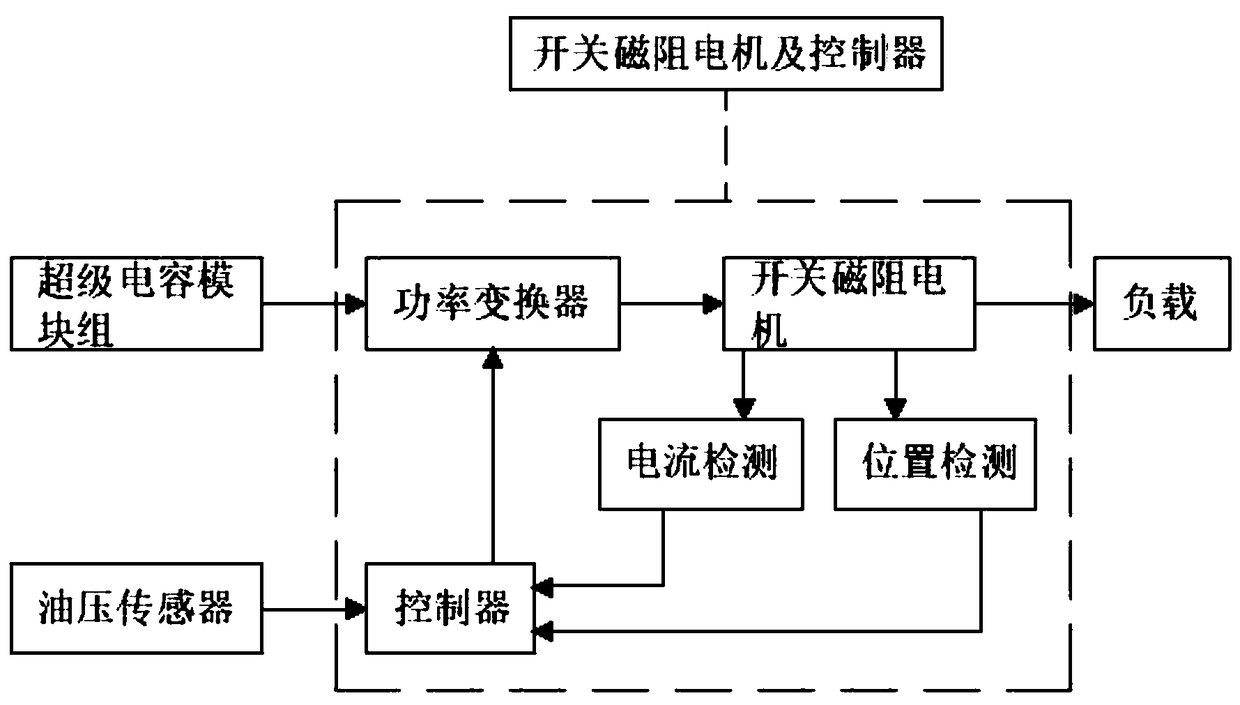
[0014] A switched reluctance motor and controller for a trailer brake and acceleration system, including a switched reluctance motor and a controller, the switched reluctance motor and a controller include a switched reluctance motor and a controller, and the switched reluctance motor passes through The current detection module and the position detection module communicate with the controller. After receiving the signal from the external oil pressure sensor, the controller further sends work instructions to the switched reluctance motor through the power converter. The power converter and the external super The capacitor module group is connected in communication, and the switched reluctance motor is connected to the external load module by transmission.

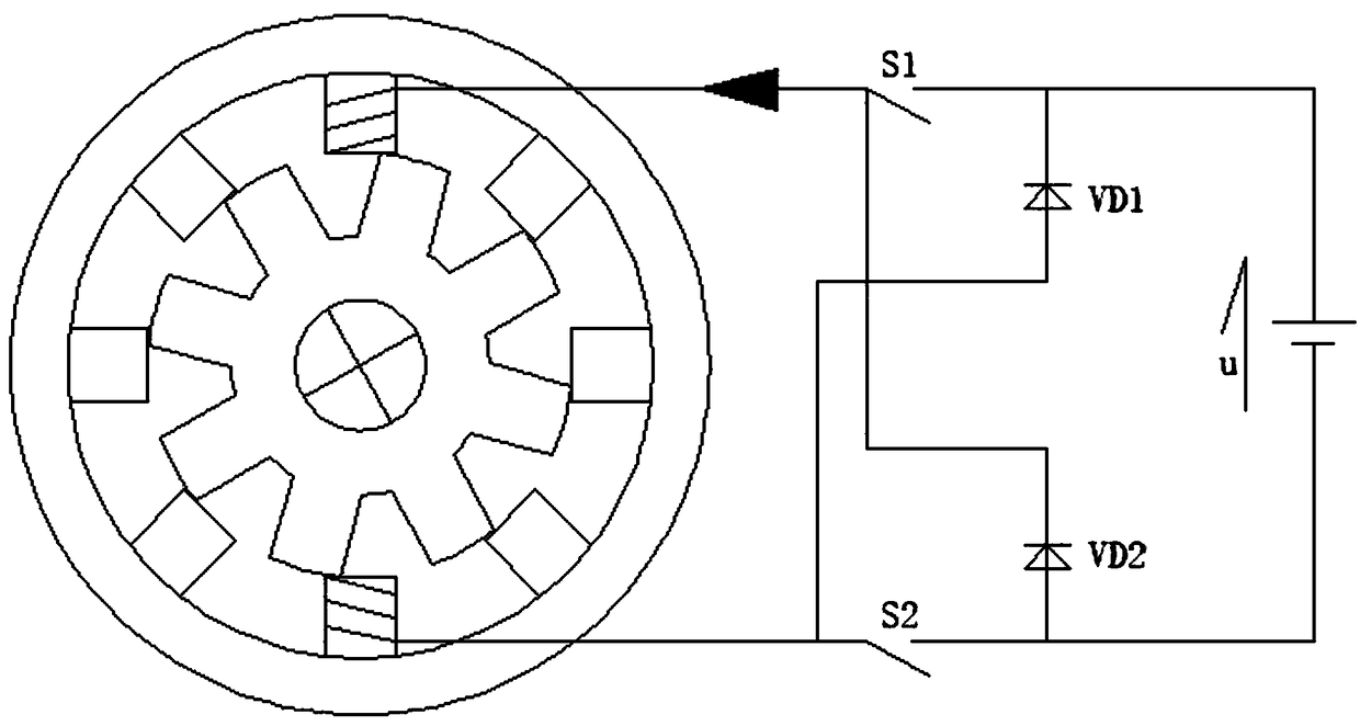
[0015] Preferably, the switched reluctance motor is a variable reluctance motor with double salient poles, and the salient poles of the stator and the rotor of the switched reluctance motor are formed by laminating silicon st...


PUM


Abstract

The invention relates to the technical field of electric vehicle control, in particular to a switched reluctance motor and controller for a trailer braking and acceleration system, which comprises a switched reluctance motor and a controller, wherein the switched reluctance motor communicates with the controller through a current detection module and a position detection module; the controller receives signals given by an external oil pressure sensor and further sends a working instruction to the switched reluctance motor through a power converter; the power converter communicates with an external supercapacitor module group; and the switched reluctance motor is in drive connection with an external load module. The switched reluctance motor and controller for the trailer braking and acceleration system has the beneficial effects that the structure is simpler than that of a squirrel-cage induction motor, the cost is low, the circuit is simple and reliable, the system reliability is high, the starting torque is large, the starting current is low, multiple controllable parameters exist, the speed regulation performance is good, the efficiency is high, and the loss is small.

Description

technical field [0001] The invention relates to the technical field of electric vehicle control, in particular to a switched reluctance motor and a controller for a trailer brake and acceleration system. Background technique [0002] Almost most small passenger cars in foreign countries will tow RVs or trailers carrying goods. This can greatly improve the loading capacity of small passenger cars and meet the requirements of car owners. However, there are strict requirements for small passenger car trailers in China. Because the scheme of increasing the loading capacity of the trailer vehicle has the following problems: 1. When the vehicle accelerates rapidly, especially when accelerating rapidly uphill, due to the sudden increase of the traction force and acting on the connection point between the minibus and the trailer, In addition, most minibuses are load-bearing bodies nowadays, which can easily cause damage to the minibus, damage to the connection points, cause the trai...

Claims


Application Information

Patent Timeline
Patent Type & Authority Applications(China)
IPC IPC(8): H02P25/08
CPCH02P25/08
Inventor 毛琦
Owner 毛琦
Why Eureka
Try Eureka