Double-horn-mouth type vertical kiln lower discharging hopper structure and work method thereof

A technology with double horns and a hopper, which is applied in the field of shaft kiln, can solve problems such as the narrowing of the gap between round steel bars or even being blocked by materials, the failure of cooling air to enter the shaft kiln smoothly, and the burning of the belt conveyor of finished products, so as to achieve convenient process layout. , easy installation and maintenance, simple and compact structure

Pending Publication Date: 2019-02-05
ACRE COKING & REFRACTORY ENG CONSULTING CORP DALIAN MCC
View PDF0 Cites 1 Cited by
  • Summary
  • Abstract
  • Description
  • Claims
  • Application Information

AI Technical Summary

Problems solved by technology

[0002] For the shaft kiln with full negative pressure operation, the cooling of the calcined materials depends on the suction of the smoke exhaust machine to deliver cooling air to the shaft kiln. Several evenly spaced round steel bars are arranged on the side wall of the cone of the discharge hopper along the circumference, and the cooling air is sucked in from the gaps between the round steel bars. The gap between the steel bars leaks to other working surfaces, and the gap between the round steel bars will shrink or even be blocked by the material after working for a period of time, so that the cooling air cannot enter the shaft kiln smoothly; the temperature of the material exiting the kiln will rise , leading to the burning of the finished product belt conveyor; the shaft kiln can only reduce production or even stop production for maintenance, so it is urgent to invent a new type of discharge hopper structure that has a good cooling effect, protects the surrounding environment, and can ensure smooth production of the shaft kiln

Method used


Image

  • Double-horn-mouth type vertical kiln lower discharging hopper structure and work method thereof
  • Double-horn-mouth type vertical kiln lower discharging hopper structure and work method thereof
  • Double-horn-mouth type vertical kiln lower discharging hopper structure and work method thereof

Examples


Embodiment Construction

[0020] The specific embodiment of the present invention will be further described below in conjunction with accompanying drawing:

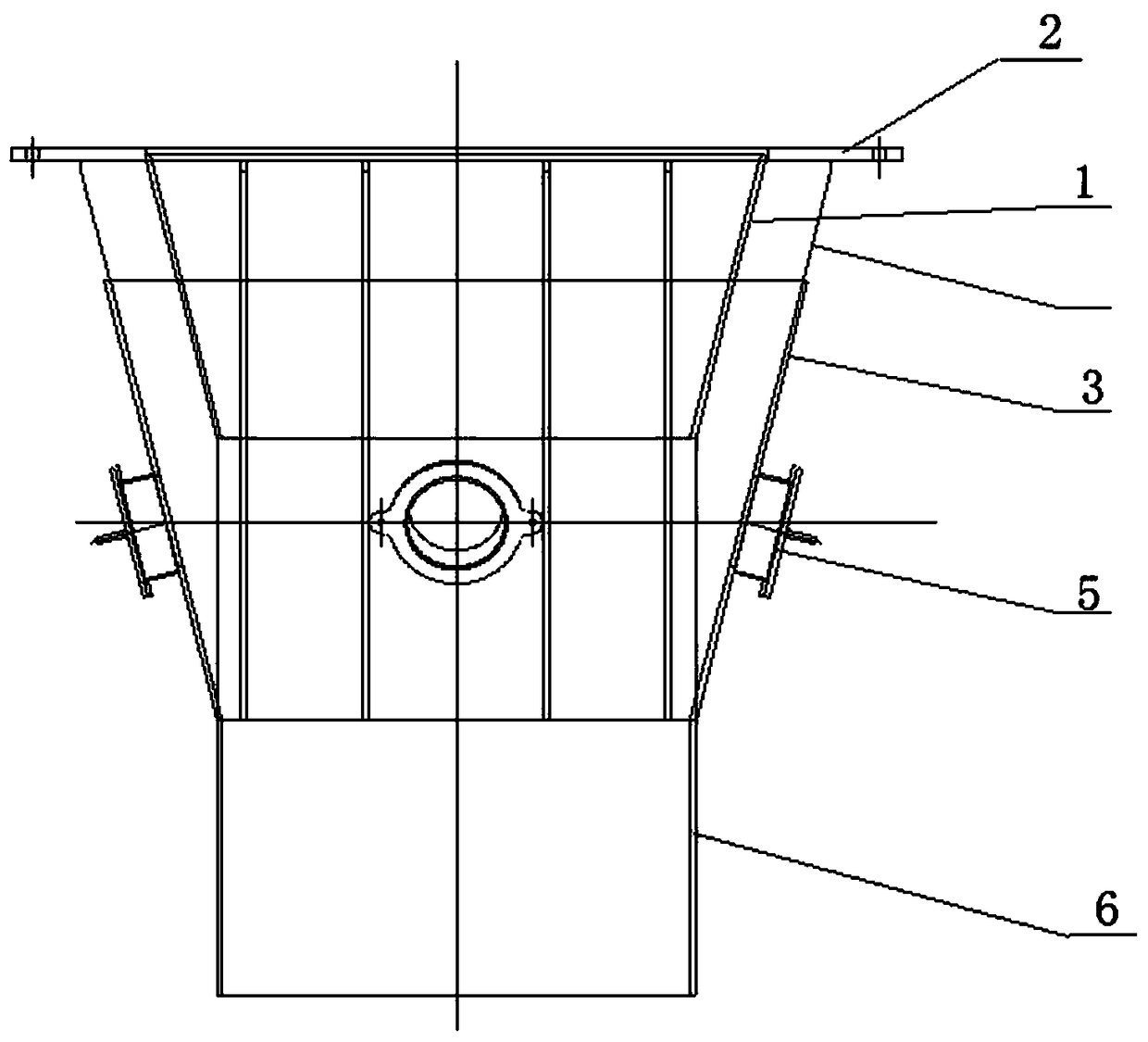
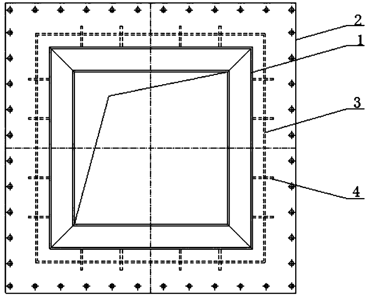
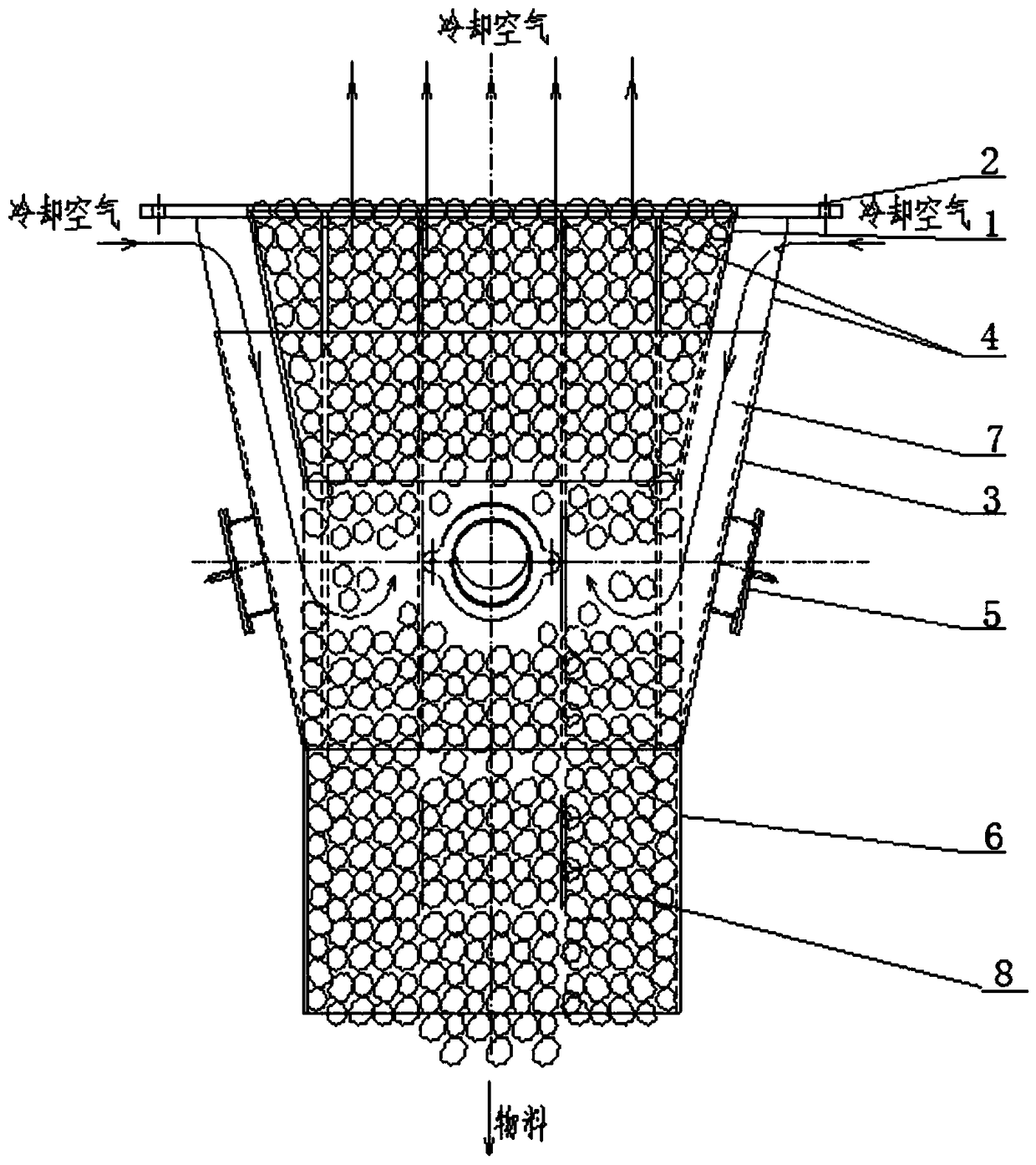
[0021] Such as figure 1 , figure 2 As shown, a double bell-mouth type shaft kiln discharge hopper structure according to the present invention is located at the lower part of the cooling section of the vertical kiln operated by full negative pressure; it includes inner peripheral groove 1, peripheral groove 3, reinforcing rib plate 4 and The straight pipe section 6, the inner peripheral groove 1 and the peripheral groove 3 are fixedly connected by a plurality of stiffener plates 4 evenly arranged along the circumferential direction; the inner peripheral groove 1 and the peripheral groove 3 both have a trumpet structure with a large top and a small bottom , there is a uniform gap between the two to form a cooling air passage 7; the top of the inner peripheral groove 1 is higher than the top of the peripheral groove 3, thereby forming a top annula...


PUM


Abstract

The invention relates to a double-horn-mouth type vertical kiln lower discharging hopper structure and a work method thereof. The discharging hopper structure comprises an inner surrounding groove, anouter surrounding groove, strengthening rib plates and a straight pipe section. The inner surrounding groove and the outer surrounding groove are fixedly connected through the multiple strengtheningrib plates. Each of the inner surrounding groove and the outer surrounding groove is provided with a horn mouth structure with a large upper part and a small lower part, and a cooling air channel is formed between the inner surrounding groove and the outer surrounding groove. The top of the inner surrounding groove is higher than the top of the outer surrounding groove, and a top annular air inletis formed in the top of the cooling air channel. The bottom of the inner surrounding groove is higher than the top of the outer surrounding groove. A bottom annular air inlet is formed in the bottomof the cooling air channel. The bottom of the outer surrounding groove is connected with the straight pipe section. In the double-horn-mouth type vertical kiln lower discharging hopper structure and the work method thereof, cooling air enters a kiln through the cooling air channel composed of the inner surrounding groove and the outer surrounding groove, it is guaranteed that the roasted materialscan be sufficiently cooled and cannot easily block a cooling air inlet, and the materials cannot leak to other worktable tops except a discharging hopper. The discharging hopper structure is simple,and manufacturing, installing and maintaining are convenient.

Description

technical field [0001] The invention relates to the technical field of shaft kilns, in particular to a double bell mouth type shaft kiln bottom discharge hopper structure and its working method. Background technique [0002] For the shaft kiln with full negative pressure operation, the cooling of the calcined materials depends on the suction of the smoke exhaust machine to deliver cooling air to the shaft kiln. Several evenly spaced round steel bars are arranged on the side wall of the cone of the discharge hopper along the circumference, and the cooling air is sucked in from the gaps between the round steel bars. The gap between the steel bars leaks to other working surfaces, and the gap between the round steel bars will shrink or even be blocked by the material after working for a period of time, so that the cooling air cannot enter the shaft kiln smoothly; the temperature of the material exiting the kiln will rise , leading to the burning of the finished product belt con...

Claims


Application Information

Patent Timeline
Patent Type & Authority Applications(China)
IPC IPC(8): F27B1/21F27B1/24F27D3/00F27D9/00
CPCF27B1/21F27B1/24F27D3/00F27D9/00F27D2009/0075
Inventor 王海波王洪涛寿庆亮赵宝海杨耕桃白城
Owner ACRE COKING & REFRACTORY ENG CONSULTING CORP DALIAN MCC
Why Eureka
Try Eureka