Parameter configuration method and device based on FPGA circuit, and storage space

A parameter configuration method and storage space technology, applied in instruments, computer control, simulators, etc., can solve the problems of long program compilation and synthesis time, low product debugging efficiency, etc., to save time, ensure confidentiality and security, The effect of improving efficiency

Active Publication Date: 2019-02-05
HUNAN AEROSPACE ELECTROMECHANICAL EQUIP & SPECIAL MATERIAL INST
View PDF8 Cites 2 Cited by
  • Summary
  • Abstract
  • Description
  • Claims
  • Application Information

AI Technical Summary

Problems solved by technology

[0007] The problem to be solved by the present invention is to provide a parameter configuration method based on an FPGA circuit for the problem that the

Method used


Image

  • Parameter configuration method and device based on FPGA circuit, and storage space
  • Parameter configuration method and device based on FPGA circuit, and storage space
  • Parameter configuration method and device based on FPGA circuit, and storage space

Examples


Embodiment

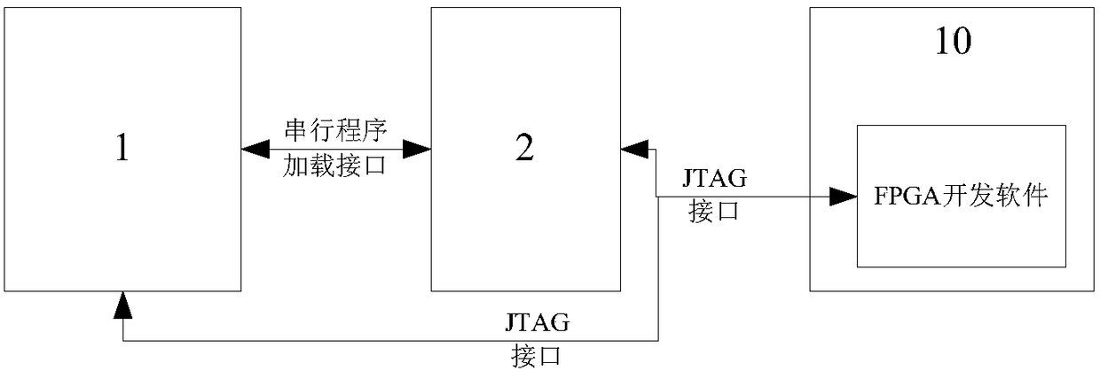
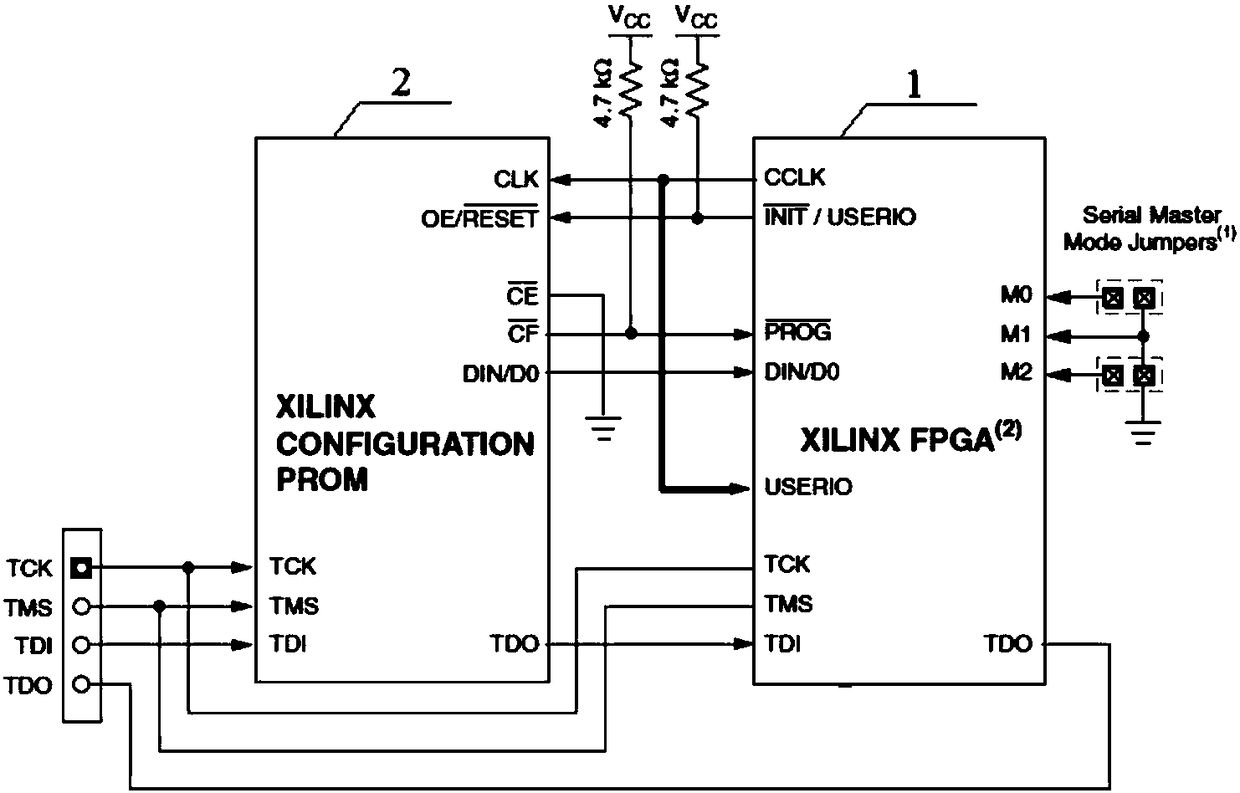
[0049] like figure 1 — Figure 10 As shown, a parameter configuration method based on FPGA circuit, the input end of FPGA circuit 1 is connected to the controlled object through A / D conversion circuit 3, and the output end of FPGA circuit 1 is connected to the controlled object through D / A conversion circuit 4 , the FPGA circuit 1 is used to control the controlled object; the PROM configuration chip 2 is connected to the FPGA circuit 1, the clock signal of the PROM configuration chip 2 is provided by the FPGA circuit 1, and the existing PROM configuration chip 2 is used to save the debugging of the gyroscope parameter. In the present invention, the fiber optic gyroscope is the controlled object.

[0050] The parameter configuration method based on FPGA circuit comprises the steps:

[0051] (A) in upper computer 10, open parameter configuration software, import the first mcs file, described first mcs file is obtained by compiling the FPGA control program of the controlled ob...


PUM


Abstract

The invention provides a parameter configuration method based on an FPGA circuit. The parameter configuration method comprises the following steps that (A) a first mcs file is imported; (B) a debugging value is assigned to to-be-debugged parameters; (C) the first mcs file is copied to obtain a second mcs file, and parameter data segments are written into the second mcs file; (D) the second mcs file is burned into a PROM configuration chip; (E) data in the PROM configuration chip are loaded into an FPGA circuit, and the to-be-debugged parameters in an FPGA control program are updated; and (F) the FPGA control program is executed, and whether an output signal of an A/D conversion circuit is normal or not is judged. The invention further provides a parameter configuration device based on theFPGA circuit, and a storage space. According to the parameter configuration method, an original FPGA control program code does not need to be modified, the multiple-time repetitive compilation and synthesis processes are omitted, and the parameter configuration method has the characteristics of good human-computer interaction, high automation degree and high debugging efficiency.

Description

technical field [0001] The invention relates to a debugging parameter configuration method of an optical fiber gyroscope, which belongs to the field of debugging of an optical fiber gyroscope. Background technique [0002] The fiber optic gyroscope is an angular velocity sensor based on the Sagnac effect. It is an all-solid-state inertial instrument with broad application prospects. It is different from traditional mechanical gyroscopes, and it has got rid of the category of rotor gyroscopes. Features such as flexible structure design. Due to its potential accuracy, fiber optic gyroscopes have replaced most of the traditional electromechanical gyroscopes in sea, land, air, and space applications, and have played a key role. [0003] The configuration parameters of the fiber optic gyroscope directly determine the final performance index. Therefore, after the gyroscope is assembled, it is necessary to debug and configure the characteristic parameters such as the time constan...

Claims


Application Information

Patent Timeline
IPC IPC(8): G05B19/042
CPCG05B19/0423G05B2219/25257
Inventor 刘智荣于中权张晓亮郭振华
Owner HUNAN AEROSPACE ELECTROMECHANICAL EQUIP & SPECIAL MATERIAL INST
Why Eureka
Try Eureka