
A method for analyzing contact stresses near singularities

A contact stress and analysis method technology, applied in special data processing applications, instruments, electrical digital data processing, etc., can solve problems such as complex forms, and achieve high operability and high engineering value.

Active Publication Date: 2019-02-05
BEIHANG UNIV
View PDF3 Cites 2 Cited by
  • Summary
  • Abstract
  • Description
  • Claims
  • Application Information

AI Technical Summary

Problems solved by technology

[0011] Therefore, most of the existing methods for solving the contact stress at singular points do not apply the contact algorithm, but use the method of constructing special units, and the construction of special units to simulate the contact behavior requires the constitutive equation of the unit to be constructed separately, and its form is very complicated

Method used


Image

  • A method for analyzing contact stresses near singularities
  • A method for analyzing contact stresses near singularities
  • A method for analyzing contact stresses near singularities

Examples


Embodiment 1

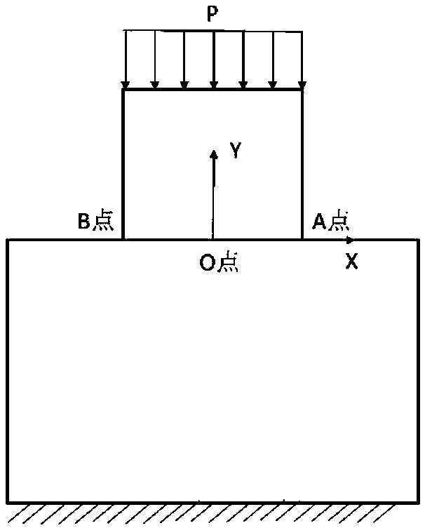
[0045] The specific steps of using the displacement extraction method to calculate the contact stress near the singular point of the 2D model are as follows:

[0046] Step 1: Establish a 2D initial contact model with sharp corners. For example, use UG to model, export the file in x_t format and import it into the finite element commercial software ANSYS through the CAD interface.

[0047] Step 2: Subnet the above initial contact model, transform it into a finite element model, set contact pairs, and apply loads and boundary conditions.

[0048]Step 3: Encrypt the mesh of the initial contact model to calculate the displacement of the singular point until the displacement converges to within 3%. In particular, when the grid is encrypted, the grid size of the subsequent encryption is half of the previous one.

[0049] Step 4: Extract the displacement deformation Ux and Uy of a series of nodes on the contact surface in the X and Y directions from the calculation results. In the...

Embodiment 2

[0062] The specific steps to calculate the contact stress near the singular point of the 3D model by using the displacement extraction method are as follows:

[0063] Step 1: Establish a 3D initial contact model. For example, use UG to model, export the file in x_t format and import it into the finite element commercial software ANSYS through the CAD interface.

[0064] Step 2: Subnet the above initial contact model, transform it into a finite element model, set contact pairs, and apply loads and boundary conditions.

[0065] Step 3: Encrypt the mesh of the initial contact model to calculate the displacement of the singular point until the displacement converges to within 3%. In particular, when the grid is encrypted, the grid size of the subsequent encryption is half of the previous one.

[0066] Step 4: Extract the displacement deformation Ux, Uy and Uz of a series of nodes on the contact surface in the X, Y and Z directions from the calculation results. In the ANSYS calc...


PUM


Abstract

A method for analyze a contact stress near a singular point is provided, characterize in that that method comprises the steps of: establishing an initial contact model; The initial contact model is meshed and transformed into a finite element model. Contact pairs are set up and loads and boundary conditions are applied. The mesh of the initial contact model is refined and the displacement of the singularity point is calculated until the displacement converges to 3%. The displacement of the interface node is extracted and output from the calculation results. Constructing high-order displacementfunction; The high-order displacement function is loaded on the contact surface, and the contact between the contact surfaces is no longer set, and the other boundary conditions remain unchanged. Regrid as in Step 3 until the contact stress at the calculated singularity converges to 5%. The new numerical analysis method of the present application can better analyze the accurate value of the contact stress near the singularity and is well applied to the engineering practice.

Description

technical field [0001] This application relates to an analysis method of contact stress, in particular to an analysis method for contact stress near a singular point. Background technique [0002] Contact calculations in complex structures must use contact numerical algorithms. At present, the commonly used contact stress calculation methods include finite element method, boundary element method and so on. Among them, the finite element method is the most widely used. When using the finite element method for contact calculations, there are generally four contact algorithms: Lagrangian, penalty function method, enhanced Lagrangian method, and Lagrangian-penalty function method. All finite element calculation methods need to carry out grid-independent detection. After the grid is doubled, if the results of the two previous and subsequent calculations are within 5%, it can be considered that the calculation structure converges with the grid refinement. This method has better...

Claims


Application Information

Patent Timeline
Patent Type & Authority Applications(China)
IPC IPC(8): G06F17/50
CPCG06F30/23G06F30/13Y02T90/00
Inventor 申秀丽张硕高鹏新董少静
Owner BEIHANG UNIV
Learn More