A high stem crop binding device

A technology for bundling devices and crops, applied in harvesters, agriculture, applications, etc., can solve the problems of high labor intensity, low production efficiency, and low bundling operation efficiency, and achieve low operating costs, high production efficiency, and automatic packaging. The effect of tying work

Active Publication Date: 2022-03-29
湖南科洋农机制造有限公司
View PDF8 Cites 0 Cited by
  • Summary
  • Abstract
  • Description
  • Claims
  • Application Information

AI Technical Summary

Problems solved by technology

[0002] High-stalk crops such as sorghum stalks and corn stalks are one of the most ideal feeds for cattle, sheep and other livestock. The traditional harvesting method is manual harvesting, which results in high labor intensity and low production efficiency; a combination of multiple crops has been developed Harvesting machinery can realize the integrated operation of harvesting and collecting pasture crops with a plant height below 2000mm, which can greatly improve production efficiency and reduce labor intensity. It is an indispensable agricultural machinery for large-scale operations
[0003] However, at present, the types of machinery that can automatically bundle pasture crops are relatively small. Generally, semi-automatic and semi-manual bundling machinery is used to bundle pasture operations, such as bundling machinery with a rotary or arm-embracing structure. The structure is relatively simple, but the bundling efficiency is not high, and the rotary structure is mainly suitable for packing and bundling of industrial products, while the arms-arm structure is mainly suitable for bundling and bundling of forage crops with a plant height of 700-2000mm. At the same time, the existing forage varieties such as "Guimu No. 1" and other pastures with a plant height exceeding 3000mm do not have suitable baling machinery

Method used


Image

  • A high stem crop binding device
  • A high stem crop binding device
  • A high stem crop binding device

Examples


Embodiment Construction

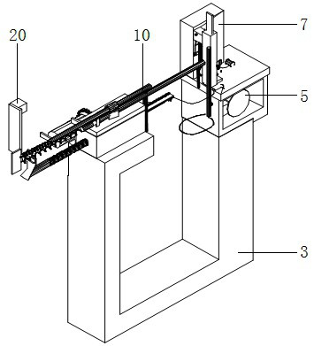
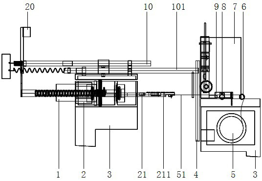
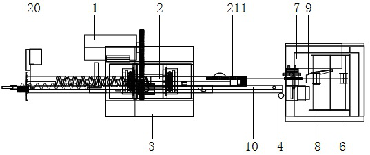
[0029] refer to Figure 1 to Figure 6 , the present invention is achieved in this way: a high-stalk crop binding device, which includes a frame 3, a driving device 1, a deceleration shuttle box assembly 2, a rope seat 5, a needle clamp 7, a rope puller 8, a breaker The rope cutter 9 and the spring identification assembly 10, the frame 3 has a U-shaped cross-section, the driving device 1, the deceleration shuttle box assembly 2 and the spring identification assembly 10 are installed on the top of one end of the U-shaped opening of the frame 3, and the The needle card 7, the rope puller 8 and the rope cutter 9 are installed on the top of the other end of the U-shaped opening of the frame 3; when the crop 30 is transported into the U-shaped opening of the frame 3, the spring identification assembly 10 measures the crop 30 to a certain level. When the weight is heavy, control the operation of the driving device 1 and drive the shuttle bar 21 to move horizontally to the other end o...


PUM


Abstract

The invention provides a high-stalk crop binding device, which includes a frame, the frame has a U-shaped cross-section, a driving device, a deceleration shuttle box assembly and a spring identification component are installed on the top of one end of the U-shaped opening of the frame, The needle card, rope puller and rope cutter are installed on the top of the other end of the U-shaped opening of the frame; when the crops are transported into the U-shaped opening of the frame, the spring identification component measures the weight of the crops and controls the operation of the driving device to make the shuttle bar move toward the machine. The other end of the U-shaped opening of the frame moves horizontally, and at the same time, the rope puller moves the tie rope to the bayonet, and then the shuttle bar drives the card needle to complete the fastening of the tie rope to the crop; it adopts the shuttle bar reciprocating type The bundling structure overcomes the defect that the existing technology is not suitable for bundling pasture crops with a plant height of more than 3000mm, and can realize automatic bundling and bundling operations, with high production efficiency, low operating costs, and firm and reliable bundling; it is widely used in various It can be used as a bundle of pasture crops.

Description

technical field [0001] The invention relates to agricultural machinery and equipment, in particular to a high-stalk crop binding device. Background technique [0002] High-stalk crops such as sorghum stalks and corn stalks are one of the most ideal feeds for cattle, sheep and other livestock. The traditional harvesting method is manual harvesting, which results in high labor intensity and low production efficiency; a combination of multiple crops has been developed Harvesting machinery can realize the integrated operation of harvesting and collecting pasture crops with a plant height of less than 2000mm, which can greatly improve production efficiency and reduce labor intensity. It is an indispensable agricultural machinery for large-scale operations. [0003] However, at present, the types of machinery that can automatically bundle pasture crops are relatively small. Generally, semi-automatic and semi-manual bundling machinery is used to bundle pasture operations, such as b...

Claims


Application Information

Patent Timeline
Patent Type & Authority Patents(China)
IPC IPC(8): A01D59/02A01D59/04A01D59/12
CPCA01D59/02A01D59/04A01D59/12
Inventor 李晚英殷增桂
Owner 湖南科洋农机制造有限公司
Why Eureka
Try Eureka