Image correction method and detection device

An image correction and detection device technology, applied in blood flow measurement devices, image enhancement, image analysis, etc., can solve the problems of reducing the accuracy of Doppler ultrasound, and achieve the effect of good detection function and accurate detection results

Active Publication Date: 2021-07-02
QISDA SUZHOU +1
View PDF6 Cites 0 Cited by
  • Summary
  • Abstract
  • Description
  • Claims
  • Application Information

AI Technical Summary

Problems solved by technology

Since the observation area of ​​the Doppler ultrasound is positioned relative to the image generated by the ultrasound, the change of the ultrasound image will also change the observation area of ​​the Doppler ultrasound, thereby reducing the accuracy of the Doppler ultrasound.

Method used


Image

  • Image correction method and detection device
  • Image correction method and detection device
  • Image correction method and detection device

Examples


no. 1 example

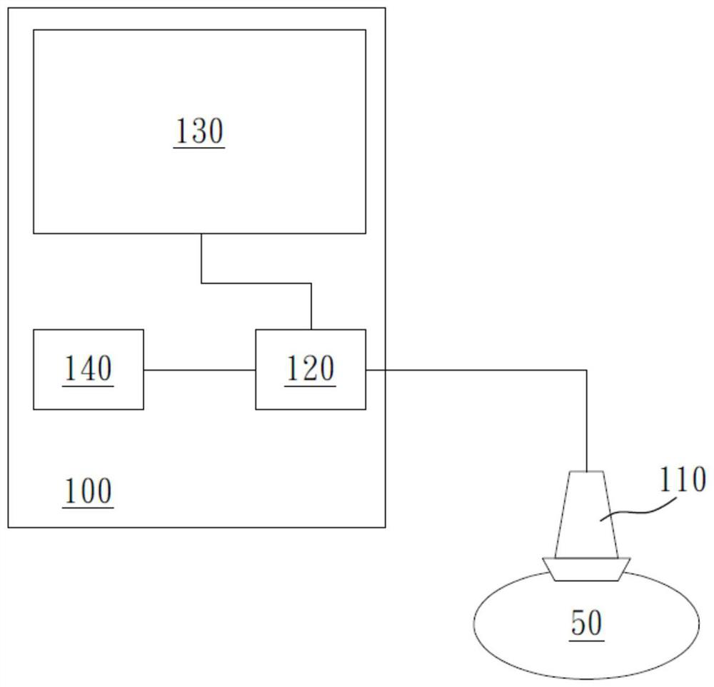
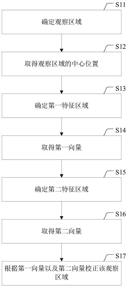
[0065] figure 2 is a schematic flowchart of the image correction method in the first embodiment of the present invention. Please refer to figure 2 , first determine the observation area in the first image frame in the dynamic image (step S11). The first image frame mentioned here can be any image frame of these image frames in the dynamic image, preferably the image frame selected by the user to determine the observation area when the user operates the image capture unit 110 .

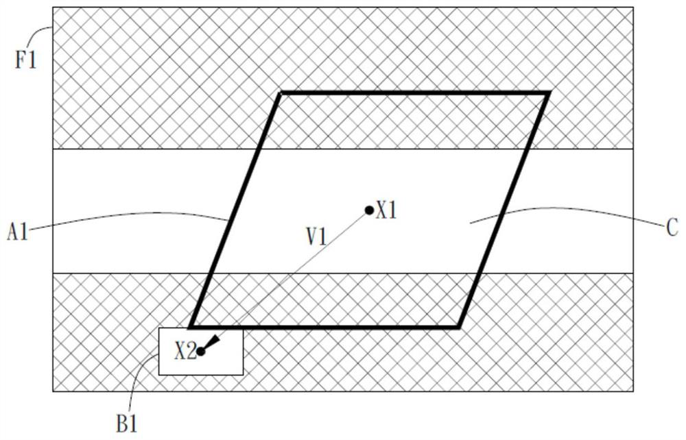
[0066] In order to clearly illustrate the image correction method proposed by the present invention, the detection device and the image correction method of the present invention will be described below with simplified image diagrams, which are not intended to limit the present invention. Please refer to figure 2 After the user determines the observation area in the first image frame (step S11), obtain the center position of the observation area in the first image frame (step S12).

[0067] Aft...

no. 2 example

[0082] The detection device and the image correction method used in the present invention can also divide the image frame into multiple sub-images to correct the observation area. Figure 6A to Figure 6D It is a schematic diagram of an image frame in the image correction method according to the second embodiment of the present invention, wherein for clarity, the black area or dark area in the image frame is drawn with hatching, and some figures are omitted to draw the colored part, so as to Each area of ​​the image frame in the present invention is clearly marked, which is not intended to limit the present invention.

[0083] Please refer to Figure 6A , in the image correction method of the second embodiment of the present invention, the image frame F4 is divided into a plurality of sub-images F41, F42, F43, F44. Specifically, after the user determines the observation area D1 in the image frame F4 and acquires the center position X5, the image frame F4 is divided into sub-im...


PUM


Abstract

The present invention provides an image correction method and detection device. The method includes: determining the observation area from the first image frame in the dynamic image, and obtaining the center position of the observation area in the first image frame; Determine the first feature region that conforms to the grayscale feature; obtain the first vector according to the center position of the first feature region in the first image frame and the center position of the observation area; in the second image frame in the dynamic image, according to the grayscale feature Find the second feature area; obtain the second vector according to the center position of the second feature area in the second image frame and the center position of the observation area; and correct the observation area in the third according to the difference between the two vectors and the first vector The position in the image frame. The image correction method and detection device provided by the present invention can maintain the observation area in an appropriate position in each image frame, thereby providing good detection function and more accurate detection results.

Description

technical field [0001] The present invention relates to a calibration method and detection device, in particular to an image calibration method and detection device Background technique [0002] Medical ultrasonography is a medical imaging diagnosis technology based on ultrasound, which can reveal the size, structure and lesions of muscles and internal organs in the human body. In the application of medical ultrasonography, Doppler ultrasound has greatly improved the capabilities of medical ultrasonography. The flow of fluid in the human body or in a living body is detected by Doppler ultrasound. For example, the flow direction and velocity of blood can be measured by Doppler ultrasound, which can provide an effective detection function in cardiovascular and other related medical fields. [0003] However, the observation area of ​​the Doppler ultrasound is mainly selected by the inspector according to the images generated by the ultrasound. Tracking a specific area in cont...

Claims


Application Information

Patent Timeline
Patent Type & Authority Patents(China)
IPC IPC(8): A61B8/00G06V10/24G06V10/25
CPCA61B8/488A61B8/58A61B8/06A61B8/5276G06T7/12G06T7/174G06T2207/10132G06V10/24G06V10/25G06V2201/03G06T5/50A61B8/0841A61B8/4444A61B8/5215G06T7/80A61B8/5207
Inventor 刘芳斌林长德
Owner QISDA SUZHOU
Why Eureka
Try Eureka