Copper rod processing equipment

A technology for processing equipment and copper rods, applied in the field of copper rod processing equipment, can solve the problems of excessive dust on the surface of copper rods, endangering the personal safety of operators, and environmental pollution.

Pending Publication Date: 2019-02-12
FOSHAN UNIVERSITY
View PDF0 Cites 2 Cited by
  • Summary
  • Abstract
  • Description
  • Claims
  • Application Information

AI Technical Summary

Problems solved by technology

[0004] The object of the present invention is to provide a copper rod processing equipment, through the cleaning cover device, the surface of the cut copper rod is cleaned, and the dust or attached copper scrap on the surface of the copper rod is removed, so as to solve the problem of excessive dust on the surface of the copper rod or Attached copper shavings will affect the appearance and quality of the copper rod; through the overall sealing structure of the equipment, the copper shavings generated by the high-speed rotating cutting knife are prevented from splashing everywhere, and the problem of copper shavings splashing everywhere due to the high-speed rotating cutting knife is solved. The problem of environmental pollution and endangering the personal safety of operators; the cooling water nozzle is used to cool down the long-term working cutting knife, which solves the problem that the cutting knife and the cutting surface of the copper rod generate heat due to the friction between the cutting knife and the blade temperature suddenly rises, which affects the service life of the cutting knife

Method used


Image

  • Copper rod processing equipment
  • Copper rod processing equipment
  • Copper rod processing equipment

Examples


Embodiment Construction

[0026] The following will clearly and completely describe the technical solutions in the embodiments of the present invention with reference to the accompanying drawings in the embodiments of the present invention. Obviously, the described embodiments are only some, not all, embodiments of the present invention. Based on the embodiments of the present invention, all other embodiments obtained by persons of ordinary skill in the art without creative efforts fall within the protection scope of the present invention.

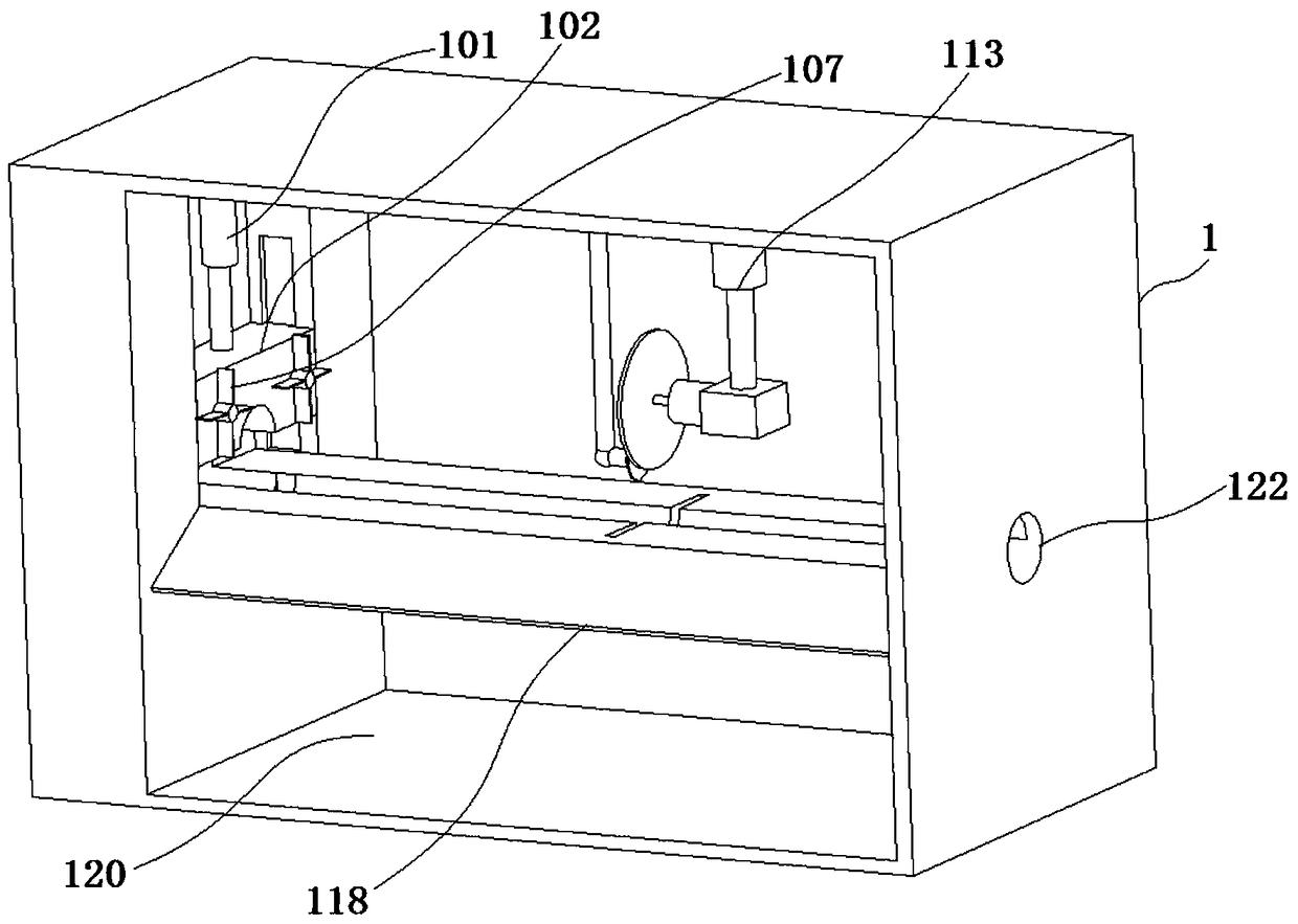
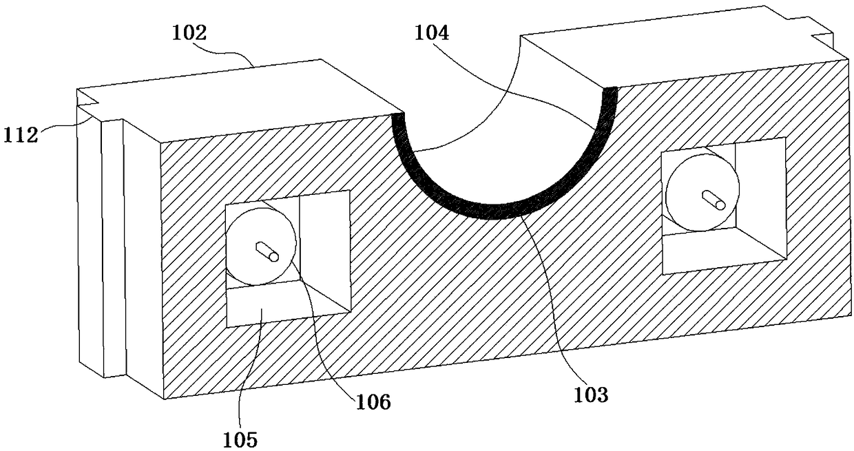
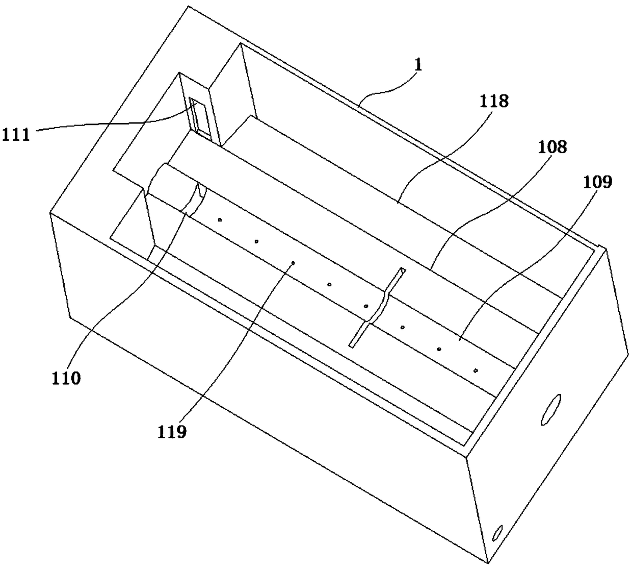
[0027] see Figure 1-3 , the present invention is a copper rod processing equipment, comprising a housing 1; the housing 1 is a closed structure; one surface of the housing 1 is fixedly connected with a first hydraulic rod 101; one end of the first hydraulic rod 101 is fixedly connected with a first block 102; the surface of the first block 102 is provided with a semicircular through hole 103; the cross section of the semicircular through hole 103 is the same as th...


PUM


Abstract

The invention discloses copper rod processing equipment, and relates to the technical field of copper rod production. The copper rod processing equipment comprises a shell, wherein a first hydraulic rod is fixedly connected to one surface of the shell; a first block is fixedly connected to one end of the first hydraulic rod; a semicircular penetrating hole is formed in one surface of the first block; a cleaning cover is fixedly connected to one surface of the semicircular penetrating hole; one end of an output shaft of a first motor penetrates through a cavity and extends to the outer side ofthe cavity; and a plurality of cleaning blades are fixedly connected to one end, which is located on the outer side of the cavity, of the output shaft of the first motor. According to the copper rod processing equipment, the surface of a copper rod which is cut is cleaned by a cleaning cover device so as to remove dust or attached copper scraps from the surface of the copper rod, so that the attractive appearance and the quality of the copper rod cannot be influenced by more dust or attached copper scraps on the surface of the copper rod; an integral sealing structure is adopted, so that copper scraps generated by cutting of a cutting knife which rotates at high speed are prevented from splattering everywhere so as not to pollute the environment or cause personal injury to operators.

Description

technical field [0001] The invention belongs to the technical field of copper rod production, and in particular relates to a copper rod processing equipment. Background technique [0002] my country is one of the first countries in the world to develop and use copper. Bronze ware was used as early as in the primitive society. In the Shang and Yin Dynasties, it reached its peak and became a treasure in the history of bronze culture in the world. Constantly improve and improve, once in a leading position in the world. The mined copper ore, after beneficiation, becomes a copper concentrate with high copper grade. It is the only metal that can be produced naturally in large quantities. It also exists in various ores. The rigidity of copper used in industry, engineering technology and technology in the form of other alloys is not very high, so some other metals are often added to support the alloy copper rod during the production process of the copper rod. [0003] The copper ro...

Claims


Application Information

Patent Timeline
Patent Type & Authority Applications(China)
IPC IPC(8): B08B1/00B23Q11/08B23Q11/10B23Q11/00
CPCB08B1/00B23Q11/00B23Q11/08B23Q11/10
Inventor 李丽芬
Owner FOSHAN UNIVERSITY
Why Eureka
Try Eureka