Machining equipment and machining method for annular groove in outer side of annular part

A technology of annular groove and processing equipment, which is applied in the field of aero-engine parts processing, can solve the problem that the fixture cannot be taken out from the part, and achieve the effect of ensuring integrity and structural stability

Active Publication Date: 2019-02-12
CHINA HANGFA SOUTH IND CO LTD
View PDF7 Cites 3 Cited by
  • Summary
  • Abstract
  • Description
  • Claims
  • Application Information

AI Technical Summary

Problems solved by technology

[0004] The invention provides a processing equipment and processing method for an outer annular groove of a ring part, in order to solve the technical problem that the existing high-temperature alloy thin-walled ring-shaped closed groove part processing method cannot remove the fixture from the part after the part is processed and formed.

Method used


Image

  • Machining equipment and machining method for annular groove in outer side of annular part
  • Machining equipment and machining method for annular groove in outer side of annular part
  • Machining equipment and machining method for annular groove in outer side of annular part

Examples


Embodiment Construction

[0026] The embodiments of the present invention will be described in detail below with reference to the accompanying drawings, but the present invention can be implemented in various ways defined and covered below.

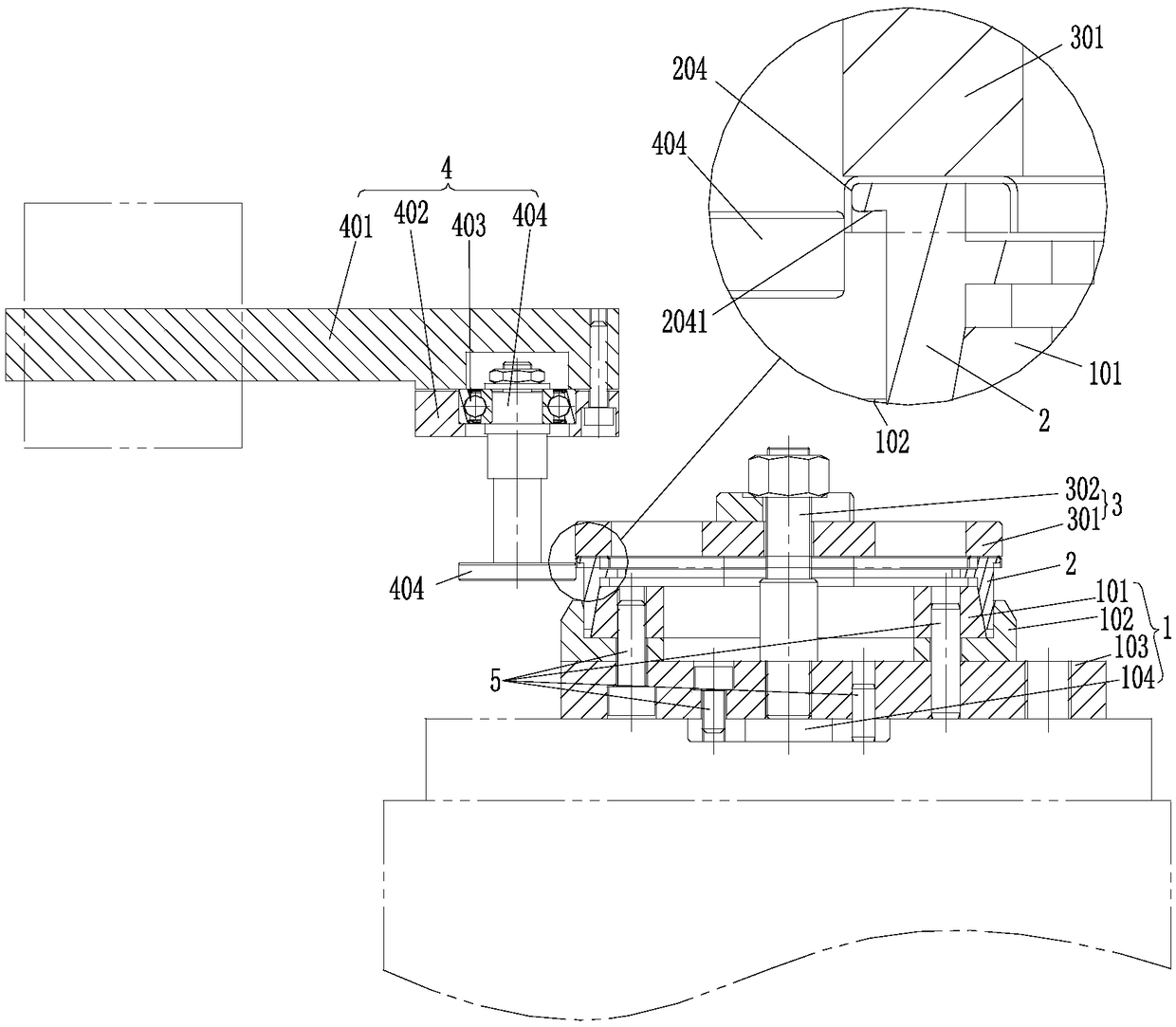
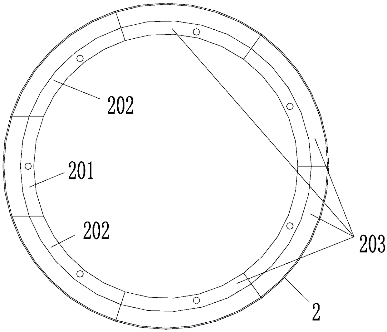
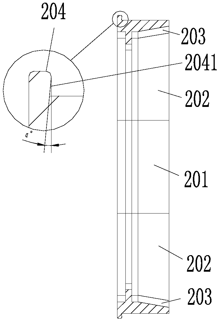
[0027] figure 1 It is a structural schematic diagram of the processing equipment for the annular groove on the outer side of the ring in the preferred embodiment of the present invention; figure 2 It is a schematic top view structure diagram of the brace assembly in the preferred embodiment of the present invention; image 3 is a schematic cross-sectional structure diagram of a brace assembly in a preferred embodiment of the present invention; Figure 4 It is a schematic diagram of the machining process of the outer ring groove of the ring member in the preferred embodiment of the present invention.

[0028] Such as figure 1 As shown, the processing equipment for the outer annular groove of the ring part in this embodiment is used for processing the outer ve...


PUM

PropertyMeasurementUnit
thicknessaaaaaaaaaa

Abstract

The invention discloses machining equipment and a machining method for an annular groove in the outer side of an annular part. The machining equipment for the annular groove in the outer side of the annular part comprises a bottom support assembly used for supporting and locating from the bottom, a shape supporting assembly fixed to the bottom support assembly and used for being supported and sleeved in a groove of a part to be machined from the bottom and forming a formed surface of the annular groove in the outer side of the part to be machined, a compression assembly located above the shapesupporting assembly and used for compressing a groove bottom plate part of the part to be machined onto the shape supporting assembly, and a spinning rolling wheel device located at the periphery ofthe shape supporting assembly and used for rolling a vertical groove wall at the outer side of the part to be machined on the shape supporting assembly in a manner of rolling to form the annular groove in the outer side, wherein the shape supporting assembly is provided with a demolding movable block used for carrying out rolling forming on the annular groove in the outer side of the part to be machined and then demolding in the radial direction of the part to be machined. The machining equipment for the annular groove in the outer side of the annular part is simple in structure, and blockingduring demolding for the part is eliminated, so that the machined part can be taken out without damage. The machining equipment and the machining method for the annular groove in the outer side of theannular part are applicable to machining and demolding for annular grooves in the outer sides of various annular parts.

Description

technical field [0001] The invention relates to the technical field of aero-engine parts processing, in particular to a processing device for an outer annular groove of an annular member. In addition, the present invention also relates to a processing method of the outer annular groove of the ring member in the processing equipment comprising the above-mentioned outer annular groove of the ring member. Background technique [0002] High-temperature alloy thin-walled annular closed groove parts belong to the component parts of aero-engines, such as Figure 5 shown. Such as Figure 6 As shown, the thickness of the part is about 0.5mm, the material is superalloy, the material strength is high, and the processing requires high forming force, and this part is a ring-shaped closed structure, and it is difficult to form local features using the traditional steel mold processing method. The surface of the medium part is under compressive stress. Due to the small enclosed space of ...

Claims


Application Information

Patent Timeline
Patent Type & Authority Applications(China)
IPC IPC(8): B21D19/02
CPCB21D19/02
Inventor 杜松夏敏李又春
Owner CHINA HANGFA SOUTH IND CO LTD
Why Eureka
Try Eureka